
I wrote this paper to make a single point: the hardware distortion (especially out-band radiation) stemming from transmitter nonlinearities in massive MIMO is a deterministic function of the transmitted signals. One consequence of this is that in most cases of practical relevance, the distortion is correlated among the antennas. Specifically, under line-of-sight propagation conditions this distortion is radiated in specific directions: in the single-user case the distortion is radiated into the same direction as the signal of interest, and in the two-user case the distortion is radiated into two other directions.
The derivation was based on a very simple third-order polynomial model. Questioning that model, or contesting the conclusions? Let’s run WebLab. WebLab is a web-server-based interface to a real power amplifier operating in the lab, developed and run by colleagues at Chalmers University of Technology in Sweden. Anyone can access the equipment in real time (though there might be a queue) by submitting a waveform and retrieving the amplified waveform using a special Matlab function, “weblab.m”, obtainable from their webpages. Since accurate characterization and modeling of amplifiers is a hard nonlinear identification problem, WebLab is a great tool to researchers who want to go beyond polynomial and truncated Volterra-type toy models.
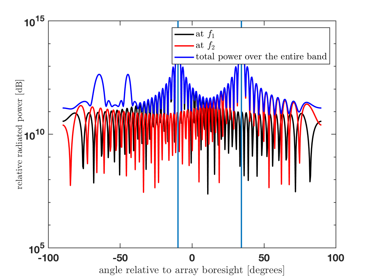
A  -spaced uniform linear array with 50 elements beamforms in free space line-of-sight to two terminals at (arbitrarily chosen) angles -9 respectively +34 degrees. A sinusoid with frequency
  is sent to the first terminal, and a sinusoid with frequency
  is transmitted to the other terminal. (Frequencies are in discrete time, see the Weblab documentation for details.) The actual radiation diagram is computed numerically: line-of-sight in free space is fairly uncontroversial: superposition for wave propagation applies. However, importantly, the actual amplification all signals is run on actual hardware in the lab.
The computed radiation diagram is shown below. (Some lines overlap.) There are two large peaks at -9 and +34 degrees angle, corresponding to the two signals of interest with frequencies  and
and  . There are also secondary peaks, at angles approximately -44 and -64 degrees, at frequencies different from respectively . These peaks originate from intermodulation products, and represent the out-band radiation caused by the amplifier non-linearity. (Homework: read the paper and verify that these angles are equal to those predicted by the theory.)
The Matlab code for reproduction of this experiment can be downloaded here.
Fundamental but perfect really!
I read some relative lectures, including your previous published ones about OOB. But, I was still little confused because channel and precoding involved.
This time, I see the fundamental formulas, very helpful to my work.
I need some help to more details for the hardware impairment components model (phase noise, I/Q imbalance, nonlinearity PA). Thank you!
One starting point is the book “RF Imperfections in High-Rate Wireless Systems: Impact and Digital Compensation” by T. Schenk, Springer 2008. There might be other, newer books or overview papers as well. Phase noise is, for example described in the introduction to this PhD thesis: http://www.diva-portal.org/smash/get/diva2:923462/FULLTEXT01.pdf And nonlinearities are discussed in the introduction to this PhD thesis: http://www.diva-portal.org/smash/get/diva2:1163832/FULLTEXT02.pdf
Very good analysis. I have one question. What will be the angles of radiated out of band distortion when these two signals (or more signals) will use the same frequency but different angles to serving users? How we can model the out of band radiation pattern for this case?
Hello Dr. Bjornson,
Thanks very much for your post. I often see that people refer to hardware impairments as another source of pilot contamination in massive MIMO systems. Could you please elaborate on how this can lead to pilot contamination? Thanks in advance.
If two users have been allocated orthogonal pilot sequences but they transmit distorted versions of them (due to hardware impairments), then the intended pilot sequences of User 1 will not be orthogonal to the distorted pilot sequence of User 2, and vice versa.
This is one of the many thing that are discussed in Chapter 6 of my book Massive MIMO networks (http://massivemimobook.com).
Could have not been better answered. Thanks a lot. In fact, I read those parts of the book before posting my question, but I got confused. It now makes more sense.