
This is supposedly a simple question to answer; an antenna is a device that emits radio waves. However, it is easy to get confused when comparing wireless communication systems with different number of transmit antennas, because these systems might use antennas with different physical sizes and properties. In fact, you can seldom find fair comparisons between contemporary single-antenna systems and Massive MIMO in the research literature.
Each antenna type has a predefined radiation pattern, which describes its inherent directivity; that is, how the gain of the emitted signal differs in different angular directions. An ideal isotropic antenna has no directivity, but a practical antenna always has a certain directivity, measured in dBi. For example, a half-wavelength dipole antenna has 2.15 dBi, which means that there is one angular direction in which the emitted signal is 2.15 dB stronger than it would be with a corresponding isotropic antenna. On the other hand, there are other angular directions in which the emitted signal is weaker. This is not a problem as long as there will not be any receivers in those directions.
In cellular communications, we are used to deploying large vertical antenna panels that cover a 120 degree horizontal sector and have a strong directivity of 15 dBi or more. Such a panel is made up of many small radiating elements, each having a directivity of a few dBi. By feeding them with the same input signal, a higher dBi is achieved for the panel. For example, if the panel consists of 8 patch antenna elements, each having 7 dBi, then you get a 7+10·log10(8) = 16 dBi antenna.
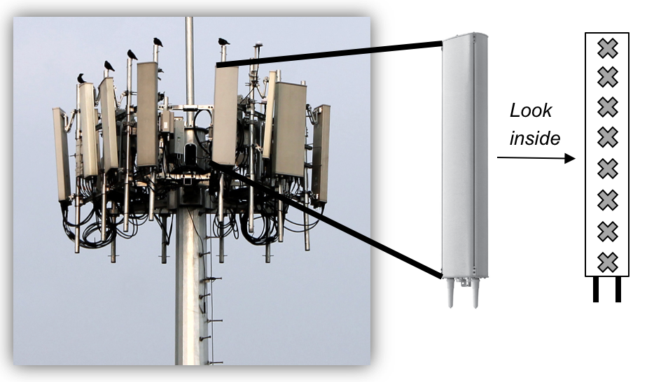
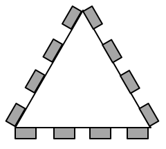 The picture above shows a real LTE site that I found in Nanjing, China, a couple of years ago. Looking at it from above, the site is structured as illustrated to the right. The site consists of three sectors, each containing a base station with four vertical panels. If you would look inside one of the panels, you will (probably) find 8 cross-polarized vertically stacked radiating elements, as illustrated in Figure 1. There are two RF input signals per panel, one per polarization, thus each panel acts as two antennas. This is how LTE with 8TX-sectors is deployed: 4 panels with dual polarization per base station.
At the exemplified LTE site, there is a total of 8·8·3 =192 radiating elements, but only 8·3 = 24 antennas. This disparity can lead to a lot of confusion. The Massive MIMO version of the exemplified LTE site may have the same form factor, but instead of 24 antennas with 16 dBi, you would have 192 antennas with 7 dBi. More precisely, you would connect each of the existing radiating elements to a separate RF input signal to create a larger number of antennas. Therefore, I suggest to use the following antenna definition from the book Massive MIMO Networks:
Definition: An antenna consists of one or more radiating elements (e.g., dipoles) which are fed by the same RF signal. An antenna array is composed of multiple antennas with individual RF chains.
Note that, with this definition, an array that uses analog beamforming (e.g., a phased array) only constitutes one antenna. It is usually called an adaptive antenna since the radiation pattern can be changed over time, but it is nevertheless a single antenna. Massive MIMO for sub-6 GHz frequencies is all about adding RF chains (also known as antenna ports), while not necessarily adding more radiating elements than in a contemporary system.
What is the purpose of having more RF chains?
With more RF chains, you have more degrees of freedom to modify the radiation pattern of the transmitted signal based on where the receiver is located. When transmitting a precoded signal to a single user, you adjust the phases of the RF input signals to make them all combine constructively at the intended receiver.
The maximum antenna/array gain is the same when using one 16 dBi antenna and when using 8 antennas with 7 dBi. In the first case, the radiation pattern is usually static and thus only a line-of-sight user located in the center of the cell sector will obtain this gain. However, if the antenna is adaptive (i.e., supports analog beamforming), the main lobe of the radiation pattern can be also steered towards line-of-sight users located in other angular directions. This feature might be sufficient for supporting the intended single-user use-cases of mm-wave technology (see Figure 4 in this paper).
In contrast, in the second case, we can adjust the radiation pattern by 8-antenna precoding to deliver the maximum gain to any user in the sector. This feature is particularly important for non-line-of-sight users (e.g., indoor use-cases), for which the signals from the different radiating elements will likely be received with “random” phase shifts and therefore add non-constructively, unless we compensate for the phases by digital precoding.
Note that most papers on Massive MIMO keep the antenna gain constant when comparing systems with different number of antennas. There is nothing wrong with doing that, but one cannot interpret the single-antenna case in such a study as a contemporary system.
Another, perhaps more important, feature of having multiple RF chains is that we can spatially multiplex several users when having multiple antennas. For this you need at least as many RF inputs as there are users. Each of them can get the full array gain and the digital precoding can be also used to avoid inter-user interference.
Dear Emil,
I have some questions, but mostly are not related with this article.
1. Let’s imagine we have a Massive MIMO antenna (128×128), do we have only one array or we can configure it to multiple ?
2. During beamforming, is the UE beamformed all the time or in some radio condition ?
3. As mentioned above, we have 128 antennas and one array. All 128 antennas are transmitting to the UE. What will happen during beamforming ? Only some antennas will be directed to the UE and what about others ?
4. In most of the articles, we see TDD is used for Massive MIMO. Why not FDD ?
Maybe my questions are funny :), thanks in advance
Hi!
1. You can deploy the antennas in any way you like. In one or multiple arrays.
2. When transmitting from an array, the signal will always be beamformed in one way or another. Maybe not in a particular angular direction, but there will always be some locations where the signal components add constructively and some locations where they combine destructively. It is always beneficial to control the beamforming so that the UE is at a location where constructive signal addition appears.
3. All antennas transmit to the user, but with different phase-shifts to make sure that constructive signal addition appears at the UE. See also: http://ma-mimo.ellintech.se/2017/10/03/what-is-the-difference-between-beamforming-and-precoding/
4. See the “grand question” in the paper: https://arxiv.org/pdf/1503.06854.pdf
Dear Emil,
I have some question, about a similar concept:
1. Is it possible to use cell sectorization techniques in 5G massive MIMO system?
2. If it is possible, the cell site may be a hotspot area in a heterogeneous network?
Thank you!
Hi!
1. Yes! For example, when using 120-degreee sectorization, each site consists of three base stations that have antenna arrays that point in different directions and form three different cells. (Each sector is a cell by itself.) All the massive MIMO theory and methods can be readily applied to that scenario.
2. I don’t see a direct connection between sectorization and heterogeneous network. Each cell/sector can either cover a hotspot or large area.
As a side note, I don’t think sectorization is needed in massive MIMO deployment. The three panels that point in different directions can be jointly used to serve all the users in the coverage area. It is better to discriminate between the users using dynamic beamforming/precoding than with fixed sectorization.
Hello Emil,
I remember from your other blogs, you said that it was not suggested to talk about directivity for digital beamforming using massive MIMO antennas because the signals travels via multi paths to the users and the precoding helps to add the signal constructively for the targeted user but destructively for other users. Does that mean that physically multiple narrow beams will bounce during the space and arrive at the target user? Do the spatially seperated beams for one target user contain the data only destined for this user? I’m still trying to get a physical image of how the beams are going to travel and in which direction for digital beamforming and I’m a still a bit puzzled. Thanks in advance.
You can view like this: There are 10 objects that the signal can bounce on and reach the user. You create one beam directed towards each one of them. Then you transmit all of these beams simultaneously and divided the power between them in an optimized manner. Figure 1 in this paper illustrates what happens: https://arxiv.org/pdf/1902.07678
Sir, Massive MIMO means multiple input multiple output.
So for multiple input there are 64 or more antennas at the base station but for to have multiple out should each User equipment have multiple antenna like (64 antenna or more)?
My question is which are the multiple inputs and which are the multiple outputs in massive MIMO?
Massive MIMO is short form for “Massive multi-user multiple-input multiple-output”.
As you say, the multiple inputs are the many antennas at the base stations. The multiple outputs are the multiple users that are served. Each user can have one or multiple antennas – it doesn’t matter in terms of the terminology.
Kindly clarify that in massive MIMO, user equipment must have multiple antenna to achieve massive MIMO gain.
Also what difference or advantage-disadvantage when user equipment have single or multiple antenna?
No, the user equipments only need a single antenna to achieve the massive MIMO gain. This is all explained in Chapter 1 of my book Massive MIMO networks (massivemimobook.com).
Remark 1.4 in the book explains what user equipments with multiple antennas can do with their antennas. It is always a benefit to have more antennas – in the worst case you just don’t use all of them…
Dear Prof. Björnson, I have some questions:
1. With UPA and fully digital beamforming, how many simultaneous beam (for LOS and NLOS case) can be created? Or how many UE can be simultaneously served in MU-MIMO?
2. Is the antenna configuration affecting the digital precoding scheme? for example: 8 antennas with different arrangement:
XXXX (cross-pol) and \ \ \ \ \ \ \ \ (same pol), both spaced half wavelength.
The first one can create 2 beams (each per pol) and the second one can create one (narrower beam with high gain) or 2 beams simultaneously.
Assuming one UE and MRT precoding, is it the same performance obtained with the two antenna configuration?
1. You can create as many beams as there are antennas. How useful that is when it comes to serving many UEs depends on how the antennas are arranged as compared to how the users are arranged. If you have a planar 8 x 8 array, you basically create a beam by choosing one out of 8 beams in the horizontal domain and one out of 8 beams in the vertical domain. If the users are only separable in the horizontal domain, you can serve up to 8 users. If the users are well separable in both the horizontal and vertical domain, you can serve up to 64 users.
2. I suppose you mean that the cross-pol case is physically smaller since antennas with different polarizations are co-located? If the aperture is smaller, the beams will be wider. The important thing for a UE is that the received signal has a polarization that matches its receive antenna. Since the orientation of the UE determines the polarization, it is good if the base station has cross-polarization so that we can be sure that one can always form a suitable beam. These things are discussed in Section 7 of my book “Massive MIMO networks”.
Thank you for your clarification. Just some thought about the two point:
1. As you point out, the number of beams is smaller or equal the number of antenna. However if the number of beam is large, then the beam will be very wide and user will suffer interference from others. In some reference, it is recommended that the number of beams should less then the number of antennas/4.
2. In this case, it is possible to use one beam for one UE, one beam with different polarization for another UE?
Could you comment on these points. Thank you.
1. Yes, but note that each beam always has the same width as if it was the only beam that was transmitted. It is the collective effect of transmitting many beams in different directions that makes the interference spread out over many directions.
2. Yes, if the users’ receive antennas are sensitive to different polarizations (e.g., rotated differently).
In general, I discourage people from thinking about beams as something having an angular directionality because that is only valid in line-of-sight communications. It is better to measure the actual channel vectors and consider how different they are.
Dear Sir, out of this topic I have a doubt/question. Please differentiate between zero forcing, MMSE and MF receiver in terms of complexity and performance. Although there is various material available on the Internet regarding the same, I am still confused about the order of complexity between these techniques.
Hi! You can find a complexity comparison in Table 4.1 and performance comparisons in Figures 4.5 and 4.6 of my book Massive MIMO networks, which you can obtain from http://massivemimobook.com
There are different forms of MMSE receiver in that table (M-MMSE, S-MMSE, and RZF). RZF has the same complexity as zero-forcing but better performance so it is recommended to use instead of zero-forcing. The MF receiver is called MR in the book.
Hi Emil,
Thanks for the great article. Just want to understand.,
1. How 192 AE is mapping into 32T32R & 64T64R antenna pattern?
2. Concept of form factor?
3. In case of 32T32R, we have 32 RF chains, so do we need 32 PA in HW architecture?
thanks.
Hi!
1. You can find some nice examples of this in the following blog post by Ericsson: https://www.ericsson.com/en/reports-and-papers/white-papers/advanced-antenna-systems-for-5g-networks
In short, they are mapping vertically adjacent antennas together, which limits the vertical resolution of the beamforming. This is the dimension there is least variability between users.
2. With that term, I meant the size of the box that is placed in the tower.
3. Yes.