
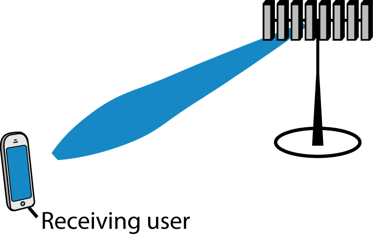
When an antenna array is used to focus a transmitted signal on a receiver, we call this beamforming (or precoding) and we usually illustrate it as shown to the right. This cartoonish illustration is only applicable when the antennas are gathered in a compact array and there is a line-of-sight channel to the receiver.
If we want to deploy very many antennas, as in Massive MIMO, it might be preferable to distribute the antennas over a larger area. One such deployment concept is called Cell-free Massive MIMO. The basic idea is to have many distributed antennas that are transmitting phase-coherently to the receiving user. In other words, the antennas’ signal components add constructively at the location of the user, just as when using a compact array for beamforming. It is therefore convenient to call it beamforming in both cases—algorithmically it is the same thing!
The question is: How can we illustrate the beamforming effect when using a distributed array?
The figure below shows how to do it. I consider a toy example with 80 star-marked antennas deployed along the sides of a square and these antennas are transmitting sinusoids with equal power, but different phases. The phases are selected to make the 80 sine-components phase-aligned at one particular point in space (where the receiving user is supposed to be):
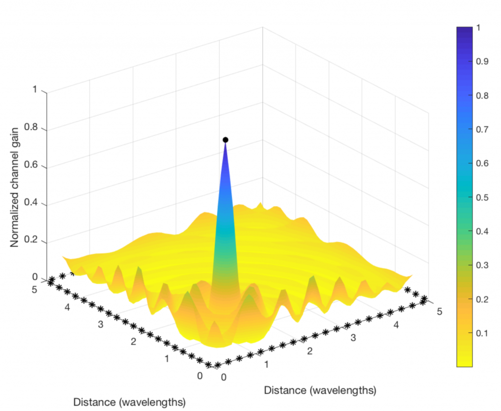
Clearly, the “beamforming” from a distributed array does not give rise to a concentrated signal beam, but the signal amplification is confined to a small spatial region (where the color is blue and the values on the vertical axis are close to one). This is where the signal components from all the antennas are coherently combined. There are minor fluctuations in channel gain at other places, but the general trend is that the components are non-coherently combined everywhere except at the receiving user. (Roughly the same will happen in a rich multipath channel, even if a compact array is used for transmission.)
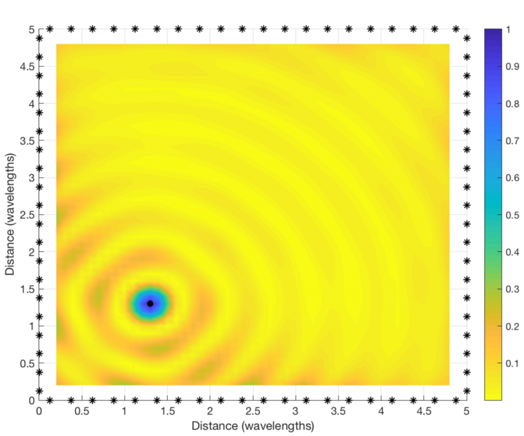
By looking at a two-dimensional version of the figure (see below), we can see that the coherent combination occurs in a circular region that is roughly half a wavelength in diameter. At the carrier frequencies used for cellular networks, this region will only be a few centimeters or millimeters wide. It is almost magical how this distributed array can amplify the signal at such a tiny spatial region! This spatial region is probably what the company Artemis is calling a personal cell (pCell) when marketing their distributed MIMO solution.
If you are into the details, you might wonder why I simulated a square region that is only a few wavelengths wide, and why the antenna spacing is only a quarter of a wavelength. This assumption was only made for illustrative purposes. If the physical antenna locations are fixed but we would reduce the wavelength, the size of the circular region will reduce and the ripples will be more frequent. Hence, we would need to compute the channel gain at many more spatial sample points to produce a smooth plot.
Reproduce the results: The code that was used to produce the plots can be downloaded from my GitHub.
Great Post!
I ran the code in Octave, except the “parula” colormap, it worked fine.
I replaced “parula” by “viridis”.
Thank you for this post! If I understood well, what is illustrated here is what happens for one user. If we imagine a scenario for multiple users (then interference will play a major role), in this case maybe zero-forcing or MRT would be applied but what will the concept of distributing many antennas bring in terms of advantages with respect to co-located classical massive MIMO setup?
Thank you,
Yes, this simulation is considering one user and MRT.
With two users, one can superimpose two figures like this on top of each other. One user gets a strong signal in one circle with diameter lambda/2 and another user gets a strong signal in another circle with diameter lambda/2.
The benefit with distributed antennas is the macro diversity gain; it is likely that some of the antennas are close to the user than it would be with a co-located array.
One would not want the antennas closer together than half a wavelength! In principle, it isn’t impossible, but it would be highly undesirable from an EM point of view (coupling, internal currents required to drive antennas etc.)
But the magic of beamforming will persist no matter the antenna spacing…
There are indeed special EM phenomena that appear when having low antenna spacing (although mutual coupling also appear with half-a-wavelength spacing), but I haven’t seen any study actually showing a degradation of the communication performance and spatial resolution.
In any case, the antenna spacing in the example was only selected to keep the size of the image down.
There are several papers that model the electromagnectics for MIMO arrays, see for example
https://mediatum.ub.tum.de/doc/1001792/1001792.pdf
Yes, I’m aware of that paper, but it doesn’t show that a clear negative impact on performance. For a fixed array size, Figs. 7-8 show that the array gain grows with the number of antennas, although the inter-antenna distance shrinks. There is an interval between lambda/2 and lambda spacing where the array gain is nearly constant, due to mutual coupling, but then it continues to grow for antenna spacings below lambda/2 as if the impact of mutual coupling gradually disappear.
From that study, one can conclude that mutual coupling is an important phenomenon but also that you don’t lose in performance from adding additional antennas into the array; in the worst case, you just don’t benefit from it.
Can you please explain eigen beamforming or linear precoding?
Linear precoding is explained in http://ma-mimo.ellintech.se/2017/10/03/what-is-the-difference-between-beamforming-and-precoding/
Eigen beamforming is a terminology that has been used for many different things, so the meaning depends on the context. But it is basically the same thing has maximum ratio precoding/transmission, where you transmit to signal in the strongest spatial direction.
In the multi-user case the following paper defines the notion of volume of coherent signal where user SINR peaks. It also provides insight into the conditions allowing such a volume to have a dimensions smaller than lambda: https://arxiv.org/abs/1601.06209
Using cooperating distributed antennas it is possible to tightly pack such volumes (well, actually the user antennas that such volumes track) and provide very large total spectral efficiency per unit volume.
Thank you for this post. I have a question about actual direction of arrival and fading coefficients for MIMO. How they are related? Just from fading coefficient can I know the DOA? Please suggest some good papers. I am confused between spatial direction and actual DOA.
The DOA is mainly of interest when is one dominant propagation path, while fading is mainly of interest when there are multiple paths.
Anyway, I recommend you to read Section 2.6 “Local Scattering Spatial Correlation Model” in my book Massive MIMO networks (https://massivemimobook.com). The phi_n parameter is the DOA of the n:th path and then we compute a spatial correlation matrix for the fading based on a random distribution of the DOAs of the multipath components.
Distributed beamforming is likely to require antenna spacing much larger than a wavelength. How much larger is feasible ?
As the antenna spacing becomes much larger than a wavelength, the wavefronts combine coherently in the desired direction as well as at other directions (grating lobes). As the antenna spacing becomes very large, these grating lobes will be very close to the
desired user. They will represent interference to other users in those grating lobe directions AND a loss of power due to radiation in the undesired directions. Is there a point where these issue become a limit how far the antennas can be spaced ?
I wouldn’t be concerned about grating lobes. The signal focusing with centralized or distributed beamforming will never be exact. The signal power that doesn’t reach the receiver can potentially leak as interference to other users, depending on where they are located. The location of the antennas will determine the spatial pattern of the interference but the average interference power is the same. Grating lobes is a big concern in localization, where it creates an ambiguity in the angle-of-arrival estimation, but not in communications.
How about the 3-dimension beamformer for distributed MIMO? Namely the spacing between the antennas are much bigger than the wavelength. Thanks
Distributed arrays can focus the signals in space, as shown in that figure, but it might not give rise to beams. The reason that angular beams are created is that many antennas are located at one location and transmit phase-shifted signals to create coherent interference in a given location. That doesn’t really happen when having well distributed antennas. Or at least you have to “zoom out” a lot to be in the far-field of a distributed array.
Thank you for this post. I have some questions about the distributed beamforming. Can you please help me answer them? I have gained some knowledge about collaborative beamforming which performs analog beamforming by a virtual antenna array. From the post, I believe that distributed beamforming is the same as collaborative beamforming. May I ask if my understanding is correct? I read some papers about collaborative beamforming, I find that there is always only one receiver at a time. Can collaborative beamforming have multiple receivers with different locations at the same time? Such as using OFDM protocol. I will appreciate your reply. Thanks.
Since MIMO communications have a long history, there can be different terms for somewhat similar things – and sometimes for exactly the same thing.
One can distinguish between the application (who is transmitting/receiving and why) and the algorithms (mathematical system models and related results).
I believe the term collaborate beamforming is often used in sensor networks when many sensors send the same signal to a common receiver, to boost the received signal power through coherent superposition.
The distributed beamforming described in this blog post is meant for multiple access points to transmit the same signal to a common user device, to maximize the received signal power through coherent superposition. The math will be quite similar even if the use case is different. When access points are transmitting, they can easily serve multiple user devices at the same time. This is what is done in cell-free massive MIMO. In principle, collaborative beamforming in sensor networks could also be used to transmit different signals to different receivers, but I’m not sure how practically interesting that is.