
If you have followed my publications on reconfigurable intelligent surfaces (RIS), also known as intelligent reflecting surfaces, you might have noticed that many of them are focusing on drawbacks that were generally overlooked when the papers were written. It could be the lack of comparison with state-of-the-art relays, the misuse of pathloss formulas designed for specular reflectors, asymptotic arguments building on formulas that break down asymptotically, the use of physically impossible channel models, or how cumbersome channel estimation generally is. However, this doesn’t mean that I’m skeptical of the technology as such. The more I have analyzed the RIS technology, the clearer it has become that there is one scenario where it works very well. In this blog post, I will explain the two criteria that must be satisfied.
Criterion 1: The direct path must be weak
Consider the following simulation example, where the respective path losses are indicated:
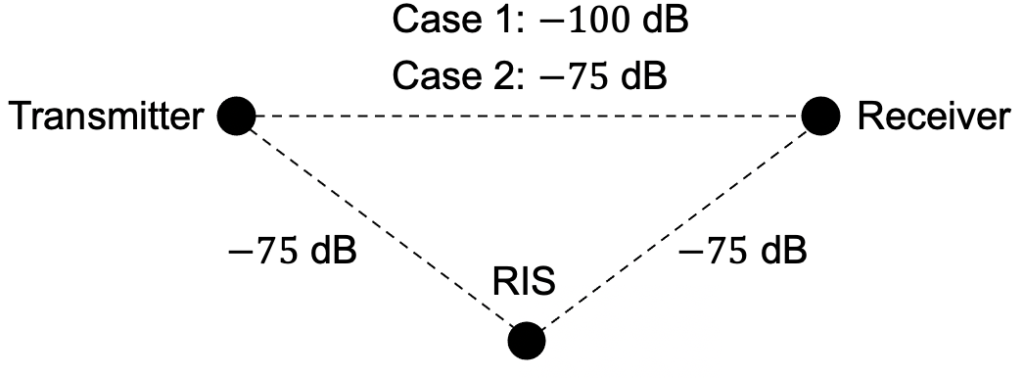
Case 1 represents a weak direct path and Case 2 represents a direct path that is of the same strength as the paths to/from the RIS. When adding more and more elements in the RIS, the spectral efficiency behaves as follows (“baseline” is the case without RIS):
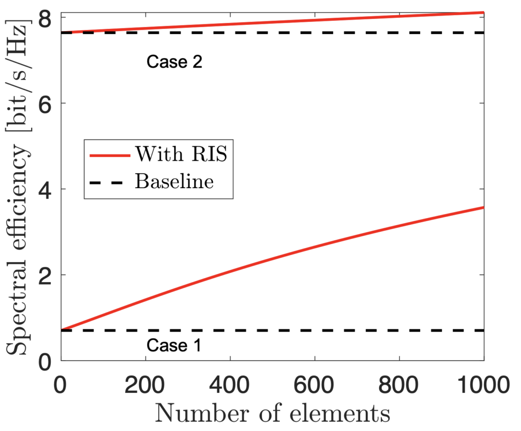
The RIS can improve the performance by a lot in Case 1 (weak direct channel), while the improvements are mediocre in Case 2 (stronger direct channel). (You can download the simulation code here.) Hence, we should utilize an RIS to improve the SNR when the channel quality is otherwise low. This might not be so surprising but it means that we must deploy the RIS strategically to get good channels both to and from it.
Criterion 2: Line-of-sight channels to and from the RIS
A more subtle point is that we should deploy the RIS to have line-of-sight channels to the transmitter and the receiver. There are three main reasons for this:
- Criterion 1 is likely to be satisfied, at least if the direct path is non-line-of-sight.
- The RIS can be used over wideband channels (e.g., tens of MHz) since most of the energy comes from one angular direction and should be delivered in one angular direction.
- The channel estimation can be vastly simplified by exploiting angular sparsity.
The following paper contains recent experimental results that demonstrate the feasibility of the RIS technology: “RIS-Aided Wireless Communications: Prototyping, Adaptive Beamforming, and Indoor/Outdoor Field Trials“. The paper describes outdoor field trials over 50 and 500 meters in scenarios satisfying the two conditions above. The paper proposes an algorithm for RIS configuration that is explicitly utilizing the angular channel sparsity and provided large SNR improvements.
I talk more about these measurements and underlying theory in the following video (which is also based on my new tutorial article):
Thanks for the nice presentation and insights Professor. I wanted to ask about the time varying character of RIS. In the tutorial article “Reconfigurable Intelligent Surfaces:
A Signal Processing Perspective With Wireless Applications”, it is mentioned that, RIS can be considered under two regimes: piecewise constant and continuously varying. In addition, in section III. C. time varying channel impulse response was given with discussion on Doppler shift and Doppler spread. I wanted to ask if there are other points in mobility that can be studied. Also, are there any references focusing on time varying regime of RIS ?
Note: I have been studying time frequency analysis during my masters and now I am wondering if some time frequency signal processing methods can be used on new communication problems. I would be grateful for any ideas on the topic. Thanks.
I have been involved in two lines of works (there might be more that I’m not aware of). The first one is about predictable mobility and how to mitigate the Doppler effects, as explained in the tutorial article and originally discussed in the following letter: https://arxiv.org/pdf/2006.06991.pdf
The second line work is about frequency-mixing surfaces: https://arxiv.org/pdf/2007.01085.pdf
Thanks for such quick response. I have actually read the first letter before writing, but I have missed the second one. Thanks a lot for your comment and for helpful presentations.
Unrelated from this post, congratulations on recent publication of your book Professor.
Many thanks for all your efforts in this blog. They are really helpful.
I have a question regarding RIS that has confused me. Generally, the reflected signal from RIS experiences strong power attenuation as there are two path loss attenuations in its way.
For estimating the cascaded channel of UE-RIS-BS, the received pilot signal would be less than the typical noise level. I am wondering how one can estimate the cascaded UE-RIS-BS with this weak received pilot signal?
For example, in your simulation example, if we send a pilot signal with 0 dB power and assume that RIS comprised of 1000 passive elements with optimal phase configuration somehow, the received pilot signal will be -120 dB which is about noise level for 20 MHz bandwidth.
This is indeed a practical challenge. The per-element SNR will be much smaller than the end-to-end SNR. However, one can increase the SNR in the estimation phase by sending pilot sequences. The SNR grows linearly with the pilot length.
Thanks a lot for all your efforts in this blog.
I have question here regarding the assumption of LoS for BS-RIS nd RIS-Rx links. Is this assumption helpful in terms of spatial multiplexing for the total effective channel between BS and Rx?
For example, if the BS-User MIMO link is Rician with strong LoS link. Does RIS help in this case for rich scattering the effective channel to be in favorable condition although the links with RIS are LoS?
Isn’t it better to deploy the RIS in a place so that it constitutes favorable conditions instead of LoS links?
Thanks
It all depends on what you mean with “favorable conditions”. If favorable = relatively strong SNR, then you need LoS links. If favorable = high rank for spatial multiplexing, then you need scattering as well. The problem with the latter case is that (a) spatial multiplexing is only useful at high SNR; (b) scattering results in frequency-selective fading, which we cannot manage effectively with an RIS.
Employing passive RIS, channel estimation algorithm is implemented at base station, since RF chains do not exist. Does the same apply for the reflection optimization algorithm (e.g. Strongest Tap Maximization in OFDM RIS-aided systems)? Could the beamforming algorithm be implemented in the RIS controller (e.g. FPGA)?
Thanks in advance.
Yes, the measurements need to made at the receiver and there must be a communication link between the RIS and receiver/transmitter. One can then either send the measurements to the RIS, which computes the preferred RIS configuration, or compute the configuration and then send it to the RIS. I think the latter is preferred since less signaling will be needed.
Thanks for your answer. Do the hardware aspects of these reflection optimization algorithms make sense (for example, a FPGA implementation of STM algorithm)? I have not seen any relevant work on this subject.
I think that practical implementation aspects are highly important to study and prototype.
Thanks for the nice insights Professor. I wanted to ask few questions regarding deployment/implementation of RIS in practical implementation scenario.
1. Who will lead the implementation of RIS equipment in 5G/Beyond 5G commercial environment? Example. Do telecom players install and operate RIS or others (government, base station manufacturers)?
2. Are there are any other leading technologies to increase coverage in 5G and Beyond 5G other than metasurface-based RIS.
These are very good questions!
1. The business model is still very unclear. In fact, it remains unclear how 5G private networks will be organized – should a building owner pay a telecom operator for it or deploy it themselves. RIS becomes even more complex since it benefits people in a limited area but must synchronize with the base station. I think the future will tell.
2. The traditional approach is repeaters and relays. The similarities and differences are discussed in https://arxiv.org/abs/2006.03377 and in https://arxiv.org/pdf/2102.00742
This is exactly how we implemented it in our proposed work.
High-Resolution Programmable Scattering for Wireless Coverage Enhancement: An Indoor Field Trial Campaign
https://arxiv.org/abs/2112.11194
Thank you Professor Bjornson for your dedicated efforts in helping us understand the theory of Reconfigurable Intelligent Surfaces (RIS). I was recently reading an article [Intelligently Wireless Batteryless RF-Powered Reconfigurable Surface: Theory, Implementation & Limitations, DOI link: 10.1109/TWC.2022.3222733], where the authors mention that the signal models commonly used in literature tend to overlook certain parameters, such as antenna structural mode and reflection efficiency. In your opinion, do you think this is indeed the case, or are these parameters implicitly included in the models we commonly find in the literature ?
The system models in the literature feature varying degrees of simplifications. One can view it as approximations that are made to enable algorithmic development and extracting qualitative insights.
If we focus on the RIS elements, you can have a look at Figure 1 in https://arxiv.org/pdf/2102.00742.pdf
The phase and amplitude responses of a particular kind of element is shown in this example. Many papers assume that all states that we can select for an element have the same amplitude response, but this won’t be the case (unless the element has 0 Ohm resistance). However, the difference is “only” 1.5 dB in this example, so it might be ok to neglect it when developing algorithms and basic theory.
Moreover, the phase response curves are not linear, as assumed in many papers, but this property holds in an interval around 3 GHz in the example, so it is a reasonable approximation if we don’t use huge amounts of spectrum.
Other properties that one could consider is how the “antenna” gain of an element depend on the incident angle and how mutual coupling can appear across closely spaced elements. The gain issue could be implicitly included in the pathloss model, while the coupling would actually change the modeling.
I think a good practice is to start analyzing a problem using simplified models and then progressively refine the models. One risk with is that researchers “get stuck” with the simple/tractable models.