
If you are an academic physical-layer researcher, like me, you might be used to treating the base station as a single unit that takes a digital data signal as input and then outputs an electromagnetic radio wave (or the opposite in the uplink). The reality is quite different, or at least it used to be.
A traditional base station consists of three main components: a baseband unit (BBU) that takes care of digital signal processing, a radio unit that creates the analog radio-frequency (RF) signal, and a passive antenna that emits the RF signals with a constant radiation pattern. Due to the size and weight constraints of masts and towers, the radio and BBU are deployed underneath and there is a long RF feeder cable between the antenna and radio, resulting in substantial power losses. This is illustrated as “Step 1” in the figure below. A single BBU can support multiple radios that are deployed on the same site, which might cover different frequency bands or cell sectors (this is not illustrated).
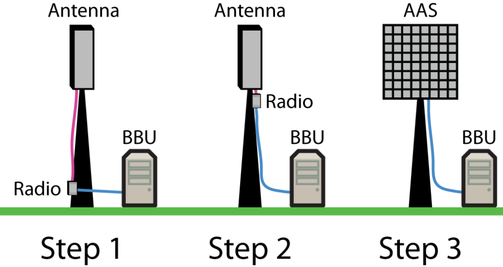
Now when the radio hardware has reduced in size, it is common to use remote radio units that are deployed in the tower, close to the antenna instead of close to the BBU. This is denoted as “Step 2” in the figure above and became common in the 4G era. Only a short RF feeder cable is then needed, while an optical fiber can be drawn from the BBU to the radio. The next step in the development is active antennas that integrate the antenna and radio into a single unit. There are many types of active antennas, from single-antenna units with constant radiation patterns to Massive MIMO antennas that adapt the radiation patterns by beamforming. To distinguish these things, the term advanced antenna system (AAS) is being used in the industry to refer to active Massive MIMO antenna arrays. This setup is denoted as “Step 3” in the figure and is becoming the dominating approach in the 5G era. To limit the capacity of the optical fiber between the AAS and BBU, an AAS might perform a limited set of baseband processing to compress/decompress the signals.
In summary, the latest radio-integrated active antennas are quite similar to what physical-layer researchers have been imaging for a while: A single unit that takes digital signals as input and emits an RF signal. Small cells can even include the BBU in the active antenna, while macro cell deployments purposely keep the BBU separate so it can be shared between multiple active antennas (it can even be moved to a nearby “cloud” computer). The advent of AAS technology is a key enabling factor for Massive MIMO deployment; a single box with 64 antennas and 64 radios can be made rather compact, while a deployment with 64 separate antenna boxes, 64 separate radio units, and an equal number of cables wouldn’t make practical sense.
BBU is referred to as Central Unit in the 5G specs. It is not possible to move the BBU to the cloud due to real-time problems. However, parts of the base station functions not dealing with real-time functions can be moved to the cloud. Examples are some protocols (RRC) and operation and maintenance. That is the idea behind V-RAN (virtualised RAN).
Yes, V-RAN can be used to virtualize higher-layer functionalities, but this is not what I had in mind when using the word “cloud”. I meant “cloud” as in cloud RAN (C-RAN), where the abbreviation can also stand for centralized RAN. In that case, the physical-layer functionalities of neighboring sites are carried out in the same edge-cloud. The deployment area that can be managed by the same unit is naturally limited by latency constraints and the speed of light.
I really appreciated your piece on Active and Passive Antennas. I have a question I would like to ask you or anyone in the forum. What is the difference between Centralized RAN and Cloud RAN? They are both abbreviated C-RAN. I have run across various explanations where it seems like there are plenty of “experts” that don’t seem to differentiate between the two. I believe I have a pretty good idea, but wouldn’t mind if someone would be knowledgeable enough on the topic to compare and contrast Centralized RAN vs. Cloud RAN. I also find that the industry does not do a good job is acronym/abbreviation distinction. Therefore, C-RAN is used in a description without clarifying which one.
I have also noticed that these terms are often used interchangeably. I think that cloud RAN is the original terminology and then the concept was generalized to centralized RAN. I would explain it like this, but I’m not sure if everyone would agree:
Distributed and centralized RAN describe the architectural difference between carrying out processing at the physical location of each base stations or centralized locations. In the centralized case, one can either use processors that are designed specifically for carrying out the required tasks (as is conventionally done in distributed RAN) or use general-purpose off-the-shelf computing hardware. The latter is what is done in cloud computing: The user doesn’t have to care about what kind of hardware that is used since the hardware will virtualize the kind of processing hardware that you would like to have. This is what is done in cloud RAN.
In summary, centralized RAN is typically implemented as cloud RAN, but there are also other options.
This is a great explanation of how base station technology has evolved! It’s fascinating to see how everything is becoming more integrated and efficient, especially with the shift to active antennas and Massive MIMO. The comparison between older setups and today’s more streamlined systems really makes it clear how much progress has been made.
RF Antenna