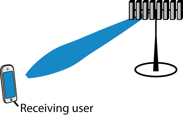
When an antenna array is used to focus a transmitted signal on a receiver, we call this beamforming (or precoding) and we usually illustrate it as shown to the right. This cartoonish illustration is only applicable when the antennas are gathered in a compact array and there is a line-of-sight channel to the receiver.
If we want to deploy very many antennas, as in Massive MIMO, it might be preferable to distribute the antennas over a larger area. One such deployment concept is called Cell-free Massive MIMO. The basic idea is to have many distributed antennas that are transmitting phase-coherently to the receiving user. In other words, the antennas’ signal components add constructively at the location of the user, just as when using a compact array for beamforming. It is therefore convenient to call it beamforming in both cases—algorithmically it is the same thing!
The question is: How can we illustrate the beamforming effect when using a distributed array?
The figure below shows how to do it. I consider a toy example with 80 star-marked antennas deployed along the sides of a square and these antennas are transmitting sinusoids with equal power, but different phases. The phases are selected to make the 80 sine-components phase-aligned at one particular point in space (where the receiving user is supposed to be):
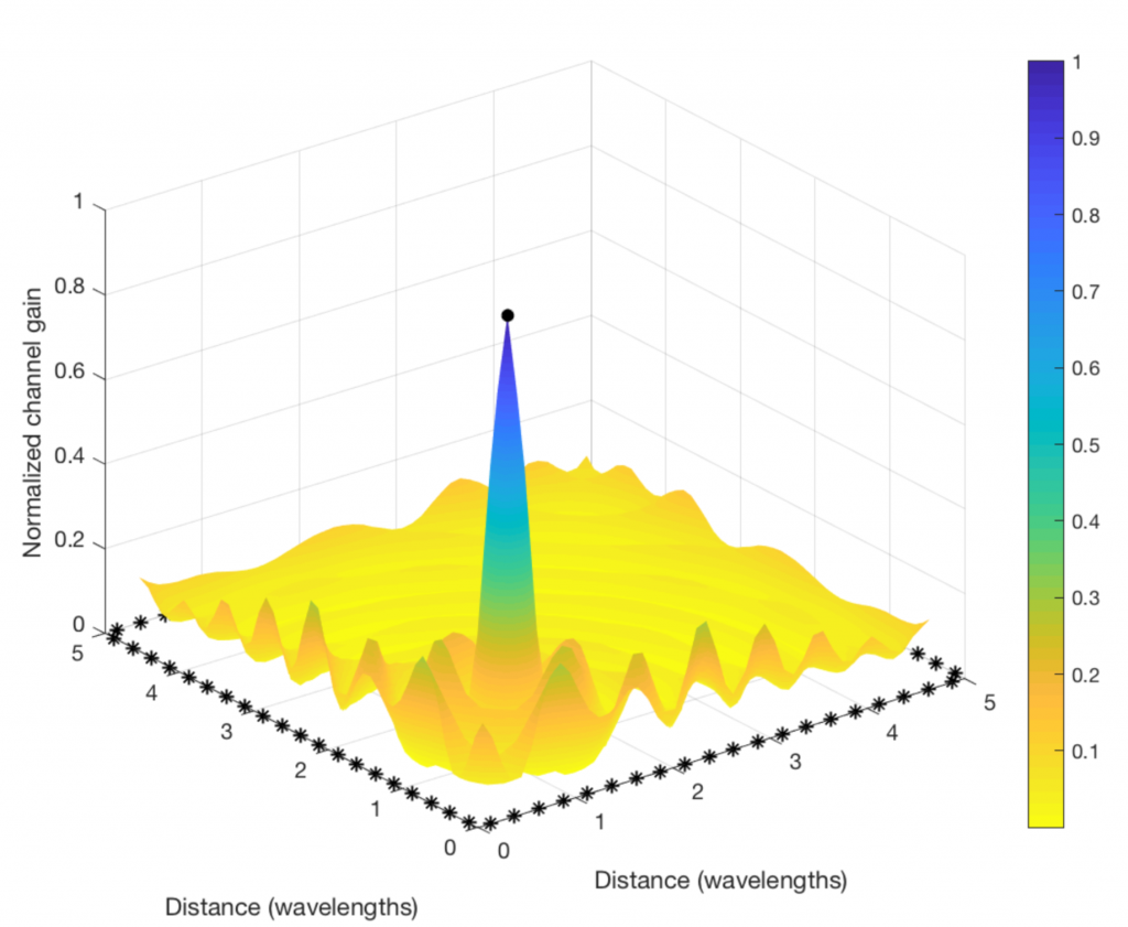
Clearly, the “beamforming” from a distributed array does not give rise to a concentrated signal beam, but the signal amplification is confined to a small spatial region (where the color is blue and the values on the vertical axis are close to one). This is where the signal components from all the antennas are coherently combined. There are minor fluctuations in channel gain at other places, but the general trend is that the components are non-coherently combined everywhere except at the receiving user. (Roughly the same will happen in a rich multipath channel, even if a compact array is used for transmission.)
By looking at a two-dimensional version of the figure (see below), we can see that the coherent combination occurs in a circular region that is roughly half a wavelength in diameter. At the carrier frequencies used for cellular networks, this region will only be a few centimeters or millimeters wide. It is almost magical how this distributed array can amplify the signal at such a tiny spatial region! This spatial region is probably what the company Artemis is calling a personal cell (pCell) when marketing their distributed MIMO solution.
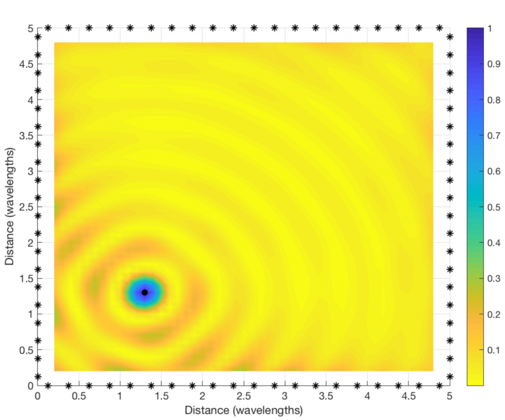
If you are into the details, you might wonder why I simulated a square region that is only a few wavelengths wide, and why the antenna spacing is only a quarter of a wavelength. This assumption was only made for illustrative purposes. If the physical antenna locations are fixed but we would reduce the wavelength, the size of the circular region will reduce and the ripples will be more frequent. Hence, we would need to compute the channel gain at many more spatial sample points to produce a smooth plot.
Reproduce the results: The code that was used to produce the plots can be downloaded from my GitHub.


