
After some successful trials, the first deployments of TDD-LTE with Massive MIMO functionality were unveiled earlier this year. For example, the telecom operator Sprint turned on Massive MIMO base stations in Chicago, Dallas, and Los Angeles last April.
If you read the press release from Sprint, it is easy to get confused regarding the number of antennas being used:
Sprint will deploy 64T64R (64 transmit, 64 receive) Massive MIMO radios using 128 antennas working with technology leaders Ericsson, Nokia, and Samsung Electronics.
From reading this quote, I get the impression that the Massive MIMO arrays contain 128 antennas, whereof 64 are used for the transmission and another 64 for the reception. That would be a poor system design, since channel reciprocity can only be exploited in TDD if the same antennas are used for both transmission and reception!
Fortunately, this is not what Sprint and other operators have actually deployed. According to my sources, the arrays contain 64 dual-polarized elements, so there are indeed 128 radiating elements. However, as I explained in a previous blog post, an antenna consists of a collection of radiating elements that are connected to the same RF chain. The number of antennas is equal to the number of RF chains, which is 64 in this case. The reason that Sprint points out that there are 64 transmit antennas and 64 receive antennas is because different RF chains are used for transmission and reception. The system switches between them according to the TDD protocol. In principle, one could design an array that has a different number of RF chains in the uplink than in the downlink, but that is not the case here.
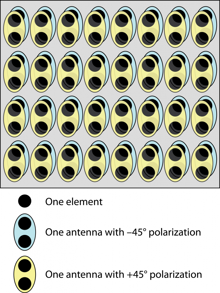 So how are the 128 elements mapped to 64 antennas (RF chains)? This is done by taking pairs of vertically adjacent elements, which have the same polarization, and connecting them to the same RF chain. This is illustrated in the figure to the right (see this blog post for pictures of how the actual arrays look like). As compared to having 128 RF chains (and antennas), this design choice results in lower flexibility in elevation beamforming, but the losses in data rates and multiplexing capability are supposed to be small since there are much larger variations in azimuth angles between the users in a cellular network than in the elevation angles. (This is explained in detail in Section 7.3-7.4 of my book). The advantage is that the implementation is more compact and less expensive when having 64 instead of 128 antennas.
I have yet to see anyone mentioning the power consumption of an antenna array whether 64, 128 antenna elements or higher. Can anyone shed light on this please?
I suppose the telecom operators will use the maximum output power that they are allowed to use. In this blog post you can find some numbers on the maximum power of a recent 64-antenna product: http://ma-mimo.ellintech.se/2018/08/27/a-look-at-an-lte-tdd-massive-mimo-product/
I have a small doubt on the antenna spacing of Massive MIMO panel in 2.5 GHz deployed by Sprint, where they mentioned 64 TRX. How is half-lambda-spacing achieved in a small device ~ near to laptop size?
Sprint is using a 64-antenna base station for LTE. It can be used to serve any LTE device/phone. One of the beauties of Massive MIMO technology is that you only need advanced hardware at the base station, while the user devices can have a single antenna and very simple. (That said, every LTE device has at least two receive antennas.)
I wanted to know optimal antenna spacing for massive MIMO. How does this antenna spacing affect the steering angle. Can you please give any reference to this. Thanks!
This is explained in Section 7.4 of the book “Massive MIMO Networks” that you can download from https://massivemimobook.com
Thanks Prof. Emil Björnson for your kind reply. I was trying to understand the reason for doing 64RF chains with 128 antennas by connecting 2 vertical antennas with the same RF. This no doubt will reduce the cost of the hardware, however comes with a cost of performance. Assuming TDD, we will not have full 128 antenna channel information due to similar antenna configuration on UL, and this limits the precoder design. Assuming MRT in the DL, where we will be matching to the DL channel, we will only have 64 antenna channel estimates and apply the same to the 128 antennas (the vertical antennas connected to same RF gets the same coefficient). Don’t this mismatch affect the performance of the DL?
Yes, it will reduce the performance, but if the MRT beamforming weights for two vertically adjacent antennas would be nearly the same, then it shouldn’t hurt much to force them to be identical. In many deployments, the users’ signals arrive to the base station from roughly the same elevation angle, which leads to almost the same MRT weights for vertically adjacent antennas. This explained in the following white paper from Ericsson (see Figure 4):
https://www.ericsson.com/en/white-papers/advanced-antenna-systems-for-5g-networks
Thanks Prof. Emil Björnson for your message and link. It definitely helps in understanding.
Hi sir, I am doing my research work on energy efficient cross layer optimization of multimedia data using fuzzy logic. I would like to ask can we use this approach in massive MIMO? One favor what topic I have to take in my PhD thesis.
I haven’t worked with cross-layer optimization with fuzzy logic myself, but I suppose it can be applied along with many different physical-layer techniques. The rate formulas for massive MIMO that you find in the book Fundamentals of Massive MIMO can be utilized for cross-layer optimization. But if you are going to work on a PhD thesis, the main question you should ask is: What are the open questions that you want to answer? It is better to start from that perspective than to start with selecting the tools that you want to use.
Sir, I want to design a MU MIMO system using a uniform planar array and optimize the training sequences. This is my PhD work on massive MIMO.
You can read about channel modeling for uniform planar arrays in Section 7.3 of my book Massive MIMO networks (https://massivemimobook.com).
As long as you use a set of orthogonal pilot sequences, it doesn’t matter what the sequences are. But you can find some examples in Section 3.1 of the book.
Excellent book!!!! Looking at 5G specifically. 3 quick questions. With 64T64R…1) how many beams can the system support during the same symbol period? 2) Can different PRB’s (allocated to different users) be beamformed in different directions? 3) If performing 5G Carrier Aggregation, can the different carriers/bands be beam formed independently at the same time?
1) I don’t know the detailed of the NR standard. In theory, you can superimpose as many beams as you like. But in practice, you don’t want more than 64 beams. 2) Yes, and you can also assign the same PRB to multiple users, if each user is using a different well-separated beam. 3) Yes.
Hi,
I want to understand if there are 64 TRXs, there will be 64 beams. However, typically only 8 to 16 layer MU-BF is supported in LTE Massive MIMO (MM) products. Is it that only a subset of 64 TRXs are used at any given instant to form beams needed for the number of paired layers/users? Or all the 64 TRXs are used dynamically all the time making narrow to wide beams as per the situation? Also, it is communicated from a vendor that currently only static beams are used by its MM products (i.e. 8 horizontal and 4 vertical beams), and each UE is assigned one of this static beam based on its location. Can this arrangement be called MM in its true spirit?
Moreover, broadcast and common control channels are not suitable for narrow beams in LTE and require one wider beam across the entire cell coverage area (65 degree to 90 degree BW), so how this broadcast beam is managed from the same MM product?
With 64 TRXs, one can create anything from one to 64 beams. One of the key features of Massive MIMO is to have many more TRXs than the number of beams that you want to form, which gives a good ability to control the directions of the beams, make the beams narrow, and suppress interference. All TRX are used at the same time. I try to explain this here: https://youtu.be/xGkyZw98Tug
Regarding “it is communicated from a vendor…. Can this arrangement be called MM in its true spirit?”: No, I wouldn’t call it Massive MIMO, but the industry has taken over the terminology and is using it for every product with at least 32 TRX.
Broadcasting from arrays can be achieved using space-time coding. Here is one algorithm for that: https://arxiv.org/pdf/1901.09554.pdf
Massive MIMO blog has a lot of information related to the 5G design. Thank you for the information.
While working on the project I have some queries related to the design criteria. Could you please help me with those topic.
1) How we can determine the number of beams can be generated for particular antenna.
E.g.:- Row=8, Column=8 and cross polar with antenna element separation =0.5λ.
2) Number of beams generation depends upon physical antenna setup or logical antenna?
3) While generating beams for 8*8 MIMO—only 21 beams generated. Is it correct?
1) Each antenna element has a fixed radiation pattern, which you might view as a single beam. However, as soon as you have two antenna elements that you can feed with different input signals, you can create an arbitrary number of different beams. So the answer is infinitely many.
2) If you are considering the number of _orthogonal_ beams that can be create simultaneously, then it is equal to the number of input signal (number of logical antennas).
3) I don’t understand where the number 21 comes from. I would say that you can simultaneously create 8 orthogonal horizontal beams and 8 orthogonal vertical beams, which then can be combined into 64 different orthogonal 3D beams.
Hi – I am having trouble understanding how an arbitrary # of beams is possible if the users are using the same subcarrier frequencies and same time slot. The weighted phase requirements for a user in 1 location may be the opposite for a user in the opposite direction so if the same frequency and timeslot is used, how can every antenna element be used for the different users..wouldnt the phase requirements for users in different locations create interference or nulling of the signal? I can understand that each user can be assigned a subarray and beams can be formed that way, but each user using the RF chain for every element at the same time on same channel seems counterintuitive to me. Thanks in advance
I think the most intuitive way of thinking about it is to design the transmission for each user separately, and then add them up (to it all at the same time). Each user prefers to use all the antennas since this creates a more strongly focused transmission, leading the maximum gain. The constructive and destructive interference pattern from the antennas will create a radiation pattern with a peak value towards the desired user and less power (sometimes nulls) in other directions. The other users will not get zero interference, but generally less interference than they would get from an omnidirectional transmission.
You then design one such directive transmission for each user and superimpose the transmissions. You transmit X different signals at the same time and frequency, each with a different directivity so that there are some locations (around the desired receiver) where it is much stronger than the X-1 other signals.
What is the benefit of doing like this instead of using one subarray per user? You can a stronger directivity and therefore less interference between the signals. The sharpness of the beam is determined by how many antennas are used when transmitting that signal. I recommend the following video, which explains the concept of beamforming using loud speakers: https://youtu.be/QwB4V8sFFnI
Thanks for your response! However, if the number of users trying to access the same freq/timeslot increases toward the # of antenna elements, wouldnt the signal essentially then just be an overall radiation pattern similar to a sector antenna with fixed pattern? If user 1 is located on 1 end of the overall horizontal beamwidth of the antenna’s capability and user 2 is located on the opposite end, wouldnt their respective phase/amplitude requirements to create their respective beam affect the other users requirements for phase/amplitude weight for their desired direction. If 1 user needs all the elements to create an extremely narrow beam and another user also needs all the elements to create the same size beam in a different direction and they are both using the same frequency and timeslot, then mixing their signals together wouldnt offset their phase/amplitude requirements?
No, the superposition principle of wave propagation says that you can transmit multiple signals at the same time without offsetting the phase and amplitudes. Antennas are not resources that become depleted when utilized. They are just radiating objects that you can radiate any summation waves.
The only issue with transmitting multiple signals is that they create interference between each other. So as the number of simultaneous beams increases towards the number of antenna elements, then the interference will increase and will eventually lower the total data throughput. For this reason, Massive MIMO is meant for having more antennas than users. For example, 64 antennas that are used for serving 8-16 users.
Hi Emil,
I am little confused on the antenna elements and its gain calculations to find out the Transmit power from each RF chain.
For eg:
Requirement is below: 16T16R, 8×4 MU MIMO or 4×2 SU MIMO with an EIRP target of 61dBm
Analysis:
Assumed 8 column antenna with 2 elements cross polarized and 4 rows. So, antenna config is 8 rows x 4 colums x 2 Pol
So the total no. of elements is 64. Ind. element gain is 5dBi. As per the theoretical calculations, the required transmit power from RF chain becomes 61-5- 10log(64)(Ant.gain)-10log(64)(BF gain) = 20dBm. Is this correct?
However, in practical, how this much gain is achieved is something i could not visualize. Because, each column has 4 radiating elements thats connected to 1 RF chain, meaning 5dBi+ 10log 4 = 11dBi is the total antenna gain. When all these 16 Tx chains are combined using beam forming, we get 10log(16)= 12dB. How we can achieve so much of gain as per the theoretical calculations?
The whole thing is required for me to design the RF FE based on the Tx power requirement and so the overall system DC consumption.
Am i missing something here?
Thanks in advance!!
Hi Ramarao,
It seems that you are calculating the same thing twice when you write 10log(64)(Ant.gain)+10log(64)(BF gain). Each antenna element has a gain of 5 dBi. With beamforming from 64 such elements, you will then have a joint antenna gain + beamforming gain of
5 + 10log10(64) = 23 dBi.
To reach all the way up to an EIRP of 61 dBm, you then need a total transmit power of 61-23 = 38 dBm = 6 W.
If you divided this power equally over the 64 elements, then each antenna element will radiate 6000/64 = 94 mW.
Thanks Emil.
So, the Tx output from 1 TRX chain has to be 94mW (19.7dBm), right? This 94 mW goes to all the 4 elements/port and becomes 19.7+10log10(4)? Is this correct?
I have 16 TRX chains and based on the current understanding, I need to have 94 mW from each TRX chain.
And is there is a dependency on the MU MIMO/ SU MIMO on the physical structure/ no. of elements of the antenna?
Also, this calculation is based on transmitting a single data stream from all 16TRX chains?
No, I mean 94 mW of radiated power per element. If you have one TRX chain connected to four elements, then you need it to provide 4*94 = 376 mW which is then divided between the elements.
The EIRP is determined by the number of elements and their individual gains and transmit power, not the number of TRX. You will achieve the strongest beam by feeding all the elements with the same signal. That can be done with one TRX connected to all elements, 16 TRX (each connected to 4 elements), or 64 TRX (each connected to one element).
It is the flexibility in what kind of signals that you transmit (e.g., number of beams and how well they can be steered) that is determined by the number of TRX. If you want to support MU-MIMO or SU-MIMO with many layers, you would like to have as many TRX as possible so you can design the signals to fit the channel as well as possible.
If we are saying 32T32R and 64T64R, I have two doubts:
1. For coverage point of view which is good, to go with 32T32R to 64T64R or if we have 32T32R we should increase the antenna elements?
2. How the antenna gain is impacted by the elements?
Please explain.
1. If you have the same number of elements, then 64T64R is more capable of changing the beamforming. Hence, it can be steered towards more locations on the cell edge. But I believe practitioners will claim that the difference is rather small.
2. It depends on what you mean with an antenna. Let’s assume that you consider an antenna port, which is an RF chain connected to multiple elements. The gain of this antenna port is equal to the gain of each element multiplied with the number of elements. (In dB scale you add the 10*log10 of the number of elements).
Thank you Emil for the post and the YouTube video for Massive MIMO.
When it comes to 64 port 5G n41 Radio head, in cable mode, in lab testing, the vendor claims that all 64 ports are configured. But only 6 (technically 8 are possible though) SSB beams are possible, on any group of 4 ports. For a device which is 4×4 capable, could you explain in this configuration, by changing the phases between various 4 ports using a phase shifter, how should we ensure whether our device is seeing a different SSB beam? I am trying to simulate a real scenario in lab using a 64×4 phase shifter.
In this config, could we see a real benefit of a 64 port Radio head with improved Throughput with two or more devices?
I’ve understood that the standard is not fully supporting the use of 64 ports, so the vendor needs to be clever in the implementation to make use of all the ports. I don’t know these implementation details.
I have a question regarding how the RF chains are connected to antenna elements. When we assume that a single RF chain is connected to a sub-array (say 4×4) in an antenna array (say 64×64). Is there a way to change the configuration (say 8×8 sub array connected to 1 RF chain) after deployment for adaptability?
The connections between RF chains and antenna elements are wired so there is not flexibility when it comes to that, but if you have subarrays of size 4×4 and wants to expand it to 8×8, you can just let 4 RF chains transmit the same signal.