
No, these are two different but somewhat related concepts, as I will explain in detail below.
Contemporary multiantenna base stations for cellular communications are equipped with 2-8 antennas, which are deployed along a horizontal line. One example is a uniform linear array (ULA), as illustrated in Figure 1 below, where the antenna spacing is uniform. All the antennas in the ULA have the same physical down-tilt, with respect to the ground, and a fixed radiation pattern and directivity.
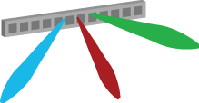
By sending the same signal from all antennas, but with different phase-shifts, we can steer beams in different angular directions and thereby make the directivity of the radiated signal different from the directivity of the individual antennas. Since the antennas are deployed on a one-dimensional horizontal line in this example, the ULA can only steer beams in the two-dimensional (2D) azimuth plane as illustrated in Figure 1. The elevation angle is the same for all beams, which is why this is called 2D beamforming. The beamwidth in the azimuth domain shrinks the more antennas are deployed. If the array is used for multiuser MIMO, then multiple beams with different azimuth angles are created simultaneously, as illustrated by the colored beams in Figure 1.

If we would rotate the ULA so that the antennas are instead deployed at different heights above the ground, then the array can instead steer beams in different elevation angles. This is illustrated in Figure 2. Note that this is still a form of 2D beamforming since every beam will have the same directivity with respect to the azimuth plane. This antenna array can be used to steer beams towards users at different floors of a building. It is also useful to serve flying objects, such as UAVs, jointly with ground users. The beamwidth in the elevation domain shrinks the more antennas are deployed.
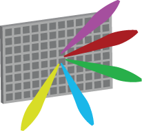
If we instead deploy multiple ULAs on top of each other, it is possible to control both the azimuth and elevation angle of a beam. This is called 3D beamforming (or full-dimensional MIMO) and is illustrated in Figure 3 using a planar array with a “massive” number of antennas. This gives the flexibility to not only steer beams towards different buildings but also towards different floors of these buildings, to provide a beamforming gain wherever the user is in the coverage area. It is not necessary to have many antennas to perform 3D beamforming – it is basically enough to have three antennas deployed in a triangle. However, as more antennas are added, the beams become narrower and easier to jointly steer in specific azimuth-elevation directions. This increases the array gain and reduces the interference between beams directed to different users, as illustrated by the colors in Figure 3.
The detailed answer to the question “3D Beamforming, is that Massive MIMO?” is as follows. Massive MIMO and 3D beamforming are two different concepts. 3D beamforming can be performed with few antennas and Massive MIMO can be deployed to only perform 2D beamforming. However, Massive MIMO and 3D beamforming is a great combination in many applications; for example, to spatially multiplex many users in a city with high-rise buildings. One should also bear in mind that, in general, only a fraction of the users are located in line-of-sight so the formation of angular beams (as shown above) might be of limited importance. The ability to control the array’s radiation pattern in 3D is nonetheless helpful to control the multipath environment such that the many signal components add constructively at the location of the intended receiver.
Dear Björnson,
As I understand here, if we have a few antennas then 3D Beamforming is possible to serve different located users. So multiple beams can be generated at same time. Right ?
— Let’s imagine, we have 64 antennas in one array antenna. And two cases:
1. All these antennas are serving a UE with a single beam. 64 antennas to one UE.
2. All these antennas are serving multiple UE at same time, with different beams. 64 antennas to different locations and different users.
What is difference between radiated signal powers between two cases?
Yes, you can do 3D beamforming with few antennas, but each beam will be wide so the users will have to be very well separated in space to avoid having large inter-user interference.
Regarding the two cases, the total radiated power of a base station is typically limited. Hence, the radiated power will be the same in both cases.
Thanks for feedback.
But regarding to the cases, I think my question was wrong. It should be “What is difference between received signal powers between two cases?”
Because, if the reason is to improve the signal in high frequency with Massive MIMO & Bemaforming. In this case the UE (one UE) should has stronger received signal strength with 64 antennas, but in the second case the signal should be less when the 64 antennas start to serve multiple UE at the same time.
Yes, the UE will have a stronger received signal strength when it is the only one being served.
But suppose there are 10 UEs to serve. How do you serve them?
1. Serve one UE at a time. Each UE is active 10% of the time, but will get a high received signal strength when it is active.
2. Serve all UEs at the same time. Each UE is active 100% of the time, but will have a lower received signal strength and also be subject to interference from the other UEs.
The second option leads to a higher data rates for every UE, as long as you have sufficiently many antennas to control the interference between the UEs.
Hi Emil, as always interesting post on the matter. Anyway, I’d like to argue about the sentence: “Massive MIMO can be deployed to only perform 2D beamforming”.
Can you comment on that? Why a massive number of antenna elements is more appropriated for a 2D array while instead, it isn’t for a UPA? I mean, Massive MIMO can be deployed also to perform 3D beamforming if it is required an extremely narrow beam in a specific azimuth-elevation direction. Am I right?
I didn’t mean that it is preferred/appropriate to deploy Massive MIMO to perform 2D beamforming, just that it is physically possible – to make the point that neither “Massive MIMO -> 3D beamforming” nor “3D beamforming -> Massive MIMO” are true implications.
My argument are not made up. You can have a look at Fig. 1 the following measurement paper: https://arxiv.org/pdf/1403.3376.pdf
The UCA will perform 3D beamforming, while the ULA will perform 2D beamforming.
If you are interested, you can read more about array deployment in Section 7.4 of my book “Massive MIMO Networks”. For example, we explain why it is preferred to have more antennas in the azimuth domain than in the elevation domain.
Dear Emil,
Thank you for your article.
I have three questions:
1- In your text, what do you mean by the ” antenna ” ?
Is it “antenna port (panel)” or “antenna element”?
2- Is the “horizontal beamforming” currently used in current LTE systems? I guess the horizontal beams are fixed and for example they are 60 or 120 degrees at the BS.
3- What is the relation between “3D beamforming” and “analog beamforming”?
Thank you very much in advance for your reply.
1. Antenna port (actually, I wouldn’t call a radiating element without an antenna port for an antenna). I elaborate on this in: http://ma-mimo.ellintech.se/2018/04/30/what-is-a-transmit-antenna/
2. I refer to 4-MIMO and 8-MIMO LTE systems. In those systems, the horizontal beams are not fixed but can be changed depending on the users. How they are changed depends on which transmission mode that is used.
3. 3D beamforming describes the geometric properties of the beamforming. Analog (versus digital) beamforming describes how it is implemented.
By 3D we normally mean Θ(the azimuth angle), ɸ(the elevation angle) and r(the distance). We can control Θ by applying appropriate phase shift between the horizontal ant array elements,ɸ by applying appropriate phase shift between the vertical ant array elements, and r by control simultaneous usage of no of ant array elements. So 3D beam forming sometimes also called FD-MIMO. But massive MIMO may not be always using all the advantages of FD-MIMO.
Hi Emil, you said ”only a fraction of the users are located in line-of-sight so the formation of angular beams….might be of limited importance”. In light of this statement how useful is 3DBF as a technology for small cell wireless backhaul in 5G Ultra Dense Network since a large number of them may be in a NLOS position? Will such backhaul be predominantly beamforming link or spatial multiplexing link? Thank you.
Hi Emil,
I have a question regarding Figure 1. When you draw multiple beams, and by saying that “sending the same signal from all antennas”, do you you mean that these beams are actually one beam but steered in different direction at different time (instead of multiple simultaneous beams)?
Another question about Hybrid beamforming: if i understand correctly, the analog BF part has a physical directivity with the physical beam pointing to the UE, and the digital BF part is the mathematical manipulation of multiple user input signals to send to different directions so that for a particular UE when receiving all the multipath propagations of the beams, will be able to construct the signal destined for this particular UE. How does the combination of Analog BF and Digital BF work?
Regarding Figure 1: With analog beamforming, one can only create one beam at a time. But I had digital beamforming in mind when drawing Figure 1 and then you can create multiple beams at the same time. As said in the text: “If the array is used for multiuser MIMO, then multiple beams with different azimuth angles are created simultaneously, as illustrated by the colored beams in Figure 1.”
Regarding hybrid beamforming: One way to view it is that the analog BF part creates the three beams in Figure 1 and then the digital BF part lets each user pick the combination of the three beams that best suites this user. Maybe you aim the three beams at three large reflecting objects that all the users see and then you find the best combinations of reflections for each user by digital BF.
Dr. Emil Björnson, I want to follow up on this question. If digital beamforming creates multiple beams at the same time, do these beams carry the same signals? In most cases, different users require different information.
Instead, if these beams are different data stream, all the antennas (port) in the whole array work for each beam or only part of the antennas produce one beam? Every port (element) send different signal, can they combine and beamform? I am not clear about how the digital beamforming operates.
Each beam carry a different signal. (If two beams would carry the same signal, then they are affectively only a single beam with a beam pattern that is a combination of the individual beams’ patterns.)
A single antenna element cannot create a beam, but only radiate a signal using its fixed antenna pattern. Hence, all the antennas are involved when forming a beam, by creating “constructive interference” between the transmitted signals at the location of the receiver.
If all the antenna elements in the whole array send the same signal with different phases, forming one beam, then, how does the array produce multible beams with different signals at a same time? Thanks.
You design the beamforming for two different signals, which each consists of sending a single signal with different phase-shifts over the antennas. Then you transmit the sum of the signals at each antenna.
You can check out my video for illustrations of this: https://youtu.be/xGkyZw98Tug
I am really looking for basic papers of mMIMO, where beam pattern optimization to reduce the max SLL for narrow band beam in the case of two dimensional (2D) active antenna arrays (AAAs) based on sub-arrays. Moreover, optimized weights give higher energy efficiency and also improved steering capability. Please share some papers. Thanks in advance.
I am not aware of any such papers. The mMIMO literature that I am familiar with is considering arbitrary antennas and array geometries. The optimization of arrays and antennas is an open problem.
1 – If we have a 64 (8 by 8) massive MIMO with 8 users in a cell, using 3D beam-forming for users, what is the range of elevation beam-width and the range of azimuth beam-width for each beam approximately?
2 – What parameters affect the range of beam-width in the case of 3D beam-forming?
1 – This depends on what what kind of antennas are used (their individual radiation patterns) and on how you measure the beamwidth (e.g., the interval that is 3 dB from the peak or the interval between two nulls).
With omnidirectional antennas in a half-wavelength-spaced 8 by 8 array, the beamwidth between two nulls is arcsin(2/8) ≈ 14.5 degrees. In other cases it is narrower than that.
2 – Array aperture/geometry, type of antennas, in which direction you point the beam, etc.
I’m thinking about 8 by 8 massive MIMO scenario in the transmitter with just a single user in the receiver side (no multiplexing). Does the transmitter still provide one beam with 8 antennas for the single user or because it’s just one user (not 8) does the transmitter use all 64 antennas to provide one narrower beam for its single user?
It is better to use all the antennas, to provide a narrower and stronger beam.
Great, Thanks Professor!
I just look up the formula that you’ve shared in “Fundamental of radar signal processing” book by Mark Richards, it says arcsin(2/N) define the 3dB bandwidth, which in this case I think FNBW (or null-to-null beamwidth) = 2*arcsin(2/8) .
You are right, I forgot the 2 in front of the arcsin.
Is it possible in a mMIMO scenario (for example with 64 antennas) after creating a beam toward the user, that beam reaches to the user through LOS path and also some reflected paths? I mean with massive MIMO and
beam-forming (here just one beam towards a user) is it still possible to have a multi-path propagation scenario?
Yes, this is how beamforming in Massive MIMO works. Maximum ratio transmission finds the way of dividing the transmit power between the different paths to maximize the SNR.
Okay, in this case the difference between multipath (in beam-forming and mMIMO) and the traditional multipath is here we will be sure that the received paths to the receiver are summed up constructively, however in the traditional multipath they could be destructive…
Yes. More precisely, there will be a “traditional multipath” between each transmit antenna and the receive antenna, but the combinations of the signals sent from the multiple transmit antennas will be summed up constructively.
Can we say that the massive MIMO system is coming under the umbrella of the beamforming concept?
Since both of them depend on the antenna structure that I have it at Tx/Rx
Depending on this structure, simply I will get 1D/2D beamforming. Having huge number of antenna elements/ports will lead to massive MIMO. Then, I can employ 3D beamforming (e.g. UPA antenna structure) and increase the number of antennas to get massive MIMO
Is this right?
No, I would rather say the opposite. Massive MIMO is an array with many “active” antennas (antenna ports), which can be used for beamforming to one user or spatial multiplexing of many users (where we transmit simultaneously to the users with different beams).
A one-dimensional Massive MIMO array can perform 2D beamforming and a two-dimensional Massive MIMO array can perform 3D beamforming.
Any reference detailing the channel model in this case and how can beamforming be done ?
Thanks
You can use any 3D channel model, see Section 7.3 in my book Massive MIMO Networks. The beamforming is done just as in any multi-user MIMO system. The modeling determines which channel realizations will be observed, while the beamforming design is more like: for a given set of channel realizations, how do we pick the beamforming vectors.
Hi Emil,
In case of 32T32R & 64T64R, can we assume that we can make 32 unique beam patterns & 64 unique beam patterns?
Is that assumption correct? or beam pattern is a different concept related to SSB & not depend on 8T8R, 32T32R& 64T64R.
Yes, you can form X non-overlapping beams with X antennas. The shape of those beams will depend on the array geometry.
Note that the users might not be located in the specific directions where the X beams are pointing, thus a key characteristic of Massive MIMO is to utilize fewer beams that the maximum in order to limit the interference.
Thanks Emil.
In digital beamforming, for 32T32R/64T64R, can I make 32/64 unique beam patterns?
What exactly is unique beam patterns here.
Can you guide how to make unique beam patterns in digital beamforming case.
Any lead or article will be helpful for 32TRX/64TRX case.
There are infinitely many unique patterns, if you mean that they are different from each other. It is just as the numbers between 0 and 1, which are infinitely many. Pick any two beams, and you can create infinitely many convex combinations of them.
I used the terminology “non-overlapping” beams. With this I mean that with X transmit antennas, you can transmit to at most X locations in such a way that each beam reaches the desired location, while it is not received at all at the X-1 undesired locations. This is achieved by a method called zero-forcing.
Hi Professor Emil,
If we consider the scenario, where we have one BS with multiple antennas and many fixed and moving UEs with both LOS and NLOS paths. My questions are:
1) How can we estimate the location of a fixed UE with a LOS path only? NLOS path(s) only? And both paths?
2) How can we estimate and track the location of a moving UE with a LOS path only? NLOS path(s) only? and both paths?
3) If a UE travels with a very high speed, say 1000 km/h, can we track this UE and steer the beam toward him?
I will appreciate any good references discussing these questions.
Hello Emil,
Could you please share a rough relation between Beam width and no of elements in both Hz and Vz directions. Also, could you please share your thoughts on the no of beams vs no of elements in a particular directions.
I can understand from Antennas perspective that we shall have quiet no of beams simultaneously using either Butler Matrix or Lens based feeds. But I would like hear your comments on the same.
With regards,
Linga,
Hi!
You can find the theory for this in Section 7.4 of my book “Massive MIMO networks” (massivemimobook.com).
For a multi-antenna array with isotropic antennas, the first-null beamwidth is roughly 2/aperture. The aperture is the length of the array, normalized by the wavelength. The half-power beamwidth is perhaps 40% of that and the use of directive antennas can further shrink the beamwidth.
Hello Emil,
Regarding uniform planar arrays, if the element spacings in both directions are less than 0.5 and the main user is at the broadside, how do we control the large lobes generated at azimuthal angles 0,pi/2,pi, and 2pi to avoid interference? or to hold favorable propagation.
Hi!
If you have shorter element spacing than 0.5, you will for sure get grating lobes. It is the equivalent of aliasing in signal transmission; the array cannot separate these directions.
To limit the impact of the grating lobes, you can use directive antennas. I guess most UPAs contain patches that only radiate in 180 degrees, so that removes the backlobe. Other grating lobes can also be damped if you have antennas with limited gain in those directions.
Generally speaking, the whole “grating lobes creates extra interference” can be misleading. Grating lobes are bad in localization because it creates ambiguity, but in communications, it just creates a particular interference pattern of the coverage area. The total interference in undesired directions will be the same. What kind of interference pattern that is desirable depends on where the other users are.
Thank you very much, professor Emil.
Hello, Prof. Emil,
If there is LoS path from BS to a reconfigurable intelligent surface (RIS) and LoS paths from RIS to Rx Bob and Rx Eve. And the positions of BS, RIS, Bob, and Eve are fixed during all the channel probings performed by BS and Bob. And the positions of scatters are also fixed during this period of time (maybe I can say this is a quasi-static environment?). And Bob and Eve are in the same direction with respect to RIS (they have the same azimuth angle and elevation angle with respect to RIS ), and they are also in the far-field of RIS. Then, if I configure RIS to beamform toward Bob, the RIS will also beamform toward Eve, is that right? Also, I think in this scenario, the magnitude of CIR between BS and Bob and the magnitude of CIR between BS and Eve would be highly correlated at the same time because the array response vectors observed by Bob and Eve can be highly correlated, is that right?
Thanks
In the setup that you describe, the channels from the RIS to Bob and Eve will be equal except for a scaling factor (describing the difference in pathloss) and possibly some diffuse scattering (if you use a Rician LOS model). Hence, any RIS configuration will be equally bad/good for both Bob and Eve.
I’m not sure what kind of correlation you are having in mind in your question. Since you consider LOS channels, most of the channel gain will come from the LOS path, which is the same for Bob and Eve.
If Bob and Eve are located in very different directions, then the channels will not be equal except for a scaling factor and beamforming towards Bob will not be the same as beamforming towards Eve.
Thanks for your reply. I am thinking about Pearson Correlation between Bob’s and Eve’s channel observations. I am thinking about building location-specific beamforming using reconfigurable Intelligent surfaces to enhance physical layer security. And what about frequency diverse array (FDA), could it be mimicked using RIS?
The setup that you describe is designed to have a large Pearson correlation, but it won’t be like that in general so it seems limiting to design a security system that requires Eve to be at “bad” locations.
I’m not particularly familiar with FDA, but an RIS can approximate the reflection/scattering behavior of any object having the same size.
Thank you, Dr. Emil Bjornson.
I see, sorry for the late reply.
Hi Prof Emil
Increasing 2D spacing results in more side lobes and grating lobes
For massive MIMO, are not these sidelobes… other spatial angles through which the signal is conveyed? Can they be considered a positive way of transmitting a 360 degrees (unequal power) but coverage for a circular array for example?
The base station generally wants the signal to be strong at the desired user location and not elsewhere, which is why the sidelobes are detrimental. The directions of the sidelobes are determined by the array geometry so they cannot be used to send information to other desired locations.
However, there exist ways to exploit both main lobes and sidelobes to transmit almost uniformly in 360 degrees. Here is a paper the describes that: https://arxiv.org/pdf/2012.02768
Hi Emil,
Can we view 3D beam forming in terms of precoding? My doubt arises because regardless of whether the antenna is a ULA or planar, the precoding will not change, given the channel vector/matrices to different users. I have read your blog on precoding and beam forming.
If you consider a specific base station and user in a specific propagation environment, the channel vector/matrix will depend on what kind of antenna arrays are used.
When I write “beamforming” in this post, I refer to the ability to form/change the directivity of the radiated signal.
The possible shapes of the radiated signal depend on the shape of the antenna array. A 1D ULA deployed in the azimuth plane can only control the shape/directivity of the signal in the azimuth plane (2D). However, a 2D array can control the directivity in all three dimensions.