
I’ve got an email with this question last week. There is not one but many possible answers to this question, so I figured that I write a blog post about it.
One answer is that beamforming and precoding are two words for exactly the same thing, namely to use an antenna array to transmit one or multiple spatially directive signals.
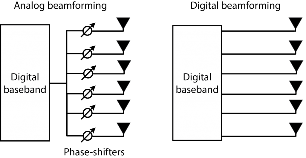
Another answer is that beamforming can be divided into two categories: analog and digital beamforming. In the former category, the same signal is fed to each antenna and then analog phase-shifters are used to steer the signal emitted by the array. This is what a phased array would do. In the latter category, different signals are designed for each antenna in the digital domain. This allows for greater flexibility since one can assign different powers and phases to different antennas and also to different parts of the frequency bands (e.g., subcarriers). This makes digital beamforming particularly desirable for spatial multiplexing, where we want to transmit a superposition of signals, each with a separate directivity. It is also beneficial when having a wide bandwidth because with fixed phases the signal will get a different directivity in different parts of the band. The second answer to the question is that precoding is equivalent to digital beamforming. Some people only mean analog beamforming when they say beamforming, while others use the terminology for both categories.
A third answer is that beamforming refers to a single-user transmission with one data stream, such that the transmitted signal consists of one main-lobe and some undesired side-lobes. In contrast, precoding refers to the superposition of multiple beams for spatial multiplexing of several data streams.
A fourth answer is that beamforming refers to the formation of a beam in a particular angular direction, while precoding refers to any type of transmission from an antenna array. This definition essentially limits the use of beamforming to line-of-sight (LoS) communications, because when transmitting to a non-line-of-sight (NLoS) user, the transmitted signal might not have a clear angular directivity. The emitted signal is instead matched to the multipath propagation so that the multipath components that reach the user add constructively.
A fifth answer is that precoding consists of two parts: choosing the directivity (beamforming) and choosing the transmit power (power allocation).
I used to use the word beamforming in its widest meaning (i.e., the first answer), as can be seen in my first book on the topic. However, I have since noticed that some people have a more narrow or specific interpretation of beamforming. Therefore, I nowadays prefer only talking about precoding. In Massive MIMO, I think that precoding is the right word to use since what I advocate is a fully digital implementation, where the phases and powers can be jointly designed to achieve high capacity through spatial multiplexing of many users, in both NLoS and LOS scenarios.
The last sentence + “in both NLOS and LOS channel.”
Yes, that is what I meant. You are right that it is important to say this explicitly when dealing with multi-antenna communications. I have updated the text. Thank you!
Can you please recommend a book, or literature where one can read thoroughly and understand the concepts of precoding?
My book “Massive MIMO networks” (massivemimobook.com) is one option. There is also the textbook Foundations of MIMO communication.
I think “Massive Precoding” would make more sense as “Precoding” is well known already in classical MIMO. By classical MIMO I mean non-massive MIMO.
Maybe a pseudo sixth answer is that precoding can be viewed as beamforming in the eigen direction of the channel rather than in any physical angular direction! However, in the TDD based massive MIMO with fewer resolvable paths (say mmWave) is it possible to set the downlink precoder as the steering matrix containing the angles of arrival estimated in the uplink? In that case, I think, the precoder maximizing the achievable rate and ‘conventional’ beamformer become similar!
You are right, eigenbeamforming is a terminology that is being used even when the eigenvector does not correspond to correspond to a physical direction.
If there is only a small number of resolvable paths, I think that the optimal precoder will be a linear combination of the steering vectors for the angles of arrivals of these paths. If the angles are all similar, the resulting beam will be almost as the steering vector of one of the angles. If the angles are very different, none of the steering vectors will be a good match.
Just curious if there is a physical description of ‘eigen-direction of the channel’? Assuming an N-by-K complex channel matrix H contains gains and phase shifts per transmit-receive antenna, how the ‘channel direction’ information is embedded in H and what it actually means.
I discourage from talking about eigen-directions of multiuser MIMO channels. It will just lead to confusion. (The terminology is more appropriate for point-to-point MIMO channels.)
With analog beamforming, changing the phase of each antenna will create a specific antenna pattern pointing to a certain direction. I am wondering if the same happens with digital beamforming?
Any analog beamforming can be implemented by digital beamforming, but the opposite is not true.
With digital beamforming you can create antenna patterns that are not achievable with analog beamforming. It will basically be a superposition of any number of analog beams, resulting in an antenna pattern that might not have a distinct direction. For example, it can be tailored to a user channel to provide a strong signal in a non-line-of-sight situation (with many multipath components in different directions). In addition to that, you can assign different antenna patterns to different parts of the frequency spectrum, while analog beamforming must assign the same phases to the entire frequency band.
Can you explain how the system detects multipath and forms its beam to better reach the receptor?
Does the receptor need to send a sortof carrier signal so the transmitter can replicate how it’s been transformed by the multiple bounces?
Yes, that is basically what is done. The transmitter sends a known signal (called a pilot) and the receiver analyzes the received signal. Since the transmitted signal is known, it can determine how the channel filtered it. It is not necessary to untangle all the multipath components but the important thing is to learn their joint effect.
Dear Prof. Emil Björnson.
Thanks for the great explanation.
You said, it can be tailored to a user channel to provide a strong signal in a non-line-of-sight situation (with many multipath components in different directions).
However, if we don’t have enough multipath components (in NLoS), will it affect the performance of digital beamforming
Here is a simple description: The NLOS channel will consist of multiple paths. Digital beamforming can be adapted to all of them, while analog beamforming must choose one to be adapted to.
The fewer paths there are, the smaller the difference will be between digital and analog beamforming.
Thank you professor for this insight “Digital beamforming can be adapted to all of them, while analog beamforming must choose one to be adapted to. The fewer paths there are, the smaller the difference will be between digital and analog beamforming”. I totally agree with you.
Hi Emil,
If we design a perfect precoding, it can create any number of beams at the same time.
(serving any number of user with perfect SINR.)
Is it right?
I’m not sure how you define “perfect precoding”.
Yes, the transmitter can transmit a superposition of any number of beams. However, the beams are not lasers but have a beamwidth determined by the aperture. If you try to send more beams than you have antennas, they will overlap in space to a large extent.
A main idea of Massive MIMO (having many more antennas than users) is to send fewer beams than you have antennas so that they won’t overlap an therefore the interference can be made small.
I really appreciate your comment.
My thought is that digital beamforming doesn’t create a physical beam (still omni-direction) but cancels the others UE’s interferences at same time through precoding. Then perfect precoding means BS can serve infinite users because we can cancel any interference.
And why is number of beams limited by number of antennas?
No, this is not how it works. Digital beamforming is a digital implementation of analog beamforming, which gives you the opportunity to send many beams at the same time.
The number of beams is not limited, but the angular width of each beam is limited by the number of antennas (the aperture of the array). So if you generate too many beams, they will be overlapping and then the interference is high.
I wonder that how can we get different directivity in different parts of the bands when phases of the signals are fixed?
Please, explain in more detail.
That is not possible and this is one of the key limitations of analog beamforming. If you have a strongly frequency-selective channel (e.g., non-line-of-sight propagation) you need different directivity in different parts of the band, which can be achieved by digital beamforming but not by analog beamforming.
Professor Bjornson – I really enjoy your Youtube videos immensely. Since I’m new to learning about massive MIMO, can you simply tell me the most practical multiplier over the current LTE spectral efficiency with Massive MIMO? I’ve read multipliers up to and beyond 50. But looking for something practical that can be implemented. Also, and equally important, how much more of a mulitiplier does beamforming add to the MIMO mutlplier? I’m looking for X and Y below — SE with mMIMO and beamforming =(1.8 b/s/Hz)X(maximum practical MIMO multiplier below 6 GHz {assume 100 antenna elements}) X (beamforming multiplier). Thank you very much!
This is a good question! I wrote a blog post to answer it properly: http://ma-mimo.ellintech.se/2018/03/23/a-basic-way-to-quantify-the-massive-mimo-gain/
Professor Bjornson thank you for this blog. I have a basic question to verify that I understood well. So if we consider ZF in massive MIMO for exemple serving simultaneously 10 users with M = 100 Tx antennas. The ZF beamformer at Tx will send signal corresponding to the different Rx users and also nulls from other antennas? The shaped beam for each user should contain the power in the estimated eigendirection and nulls I suppose from other antennas in the array?
Each channel from the 100 TX antennas to one of the Rx users is represented by a 100-length vector. When transmitting to user 1, you find a beamforming direction (i.e., a vectors) that is orthogonal to the channels of user 2,…,10, but as parallel to the channel of user 1 as is possible under the orthogonality constraint. When you have done this for every user, you take each user’s beamforming vector multiply it with the intended signal of that user and add it all up. As a consequence, every antenna sends a combination of the signals from all the users.
I’m not sure what you mean with “eigendirections” since this word has many different meanings in the literature, but it is not important here.
For more details, you can check out my article:
Emil Björnson, Mats Bengtsson, Björn Ottersten, “Optimal Multiuser Transmit Beamforming: A Difficult Problem with a Simple Solution Structure,” IEEE Signal Processing Magazine, vol. 31, no. 4, pp. 142-148, July 2014.
In LTE digital beamforming, exactly how does the precoding matrix indicator (PMI) from a UE helps eNodeB in which direction to point the beam to that UE. I mean just be multiplying the symbols with precoding weights how beam is formed pointing exactly to the UE. How the angular direction intelligence built in to the PMI and how does the UE knows such angular intelligence for eNodeB to reach it.
This is hard to answer precisely. There are many different transmission modes in LTE and what is standardized is typically what the UE should transmit and receive, while there is some flexibility in what the eNodeB can do.
However, the typical digital beamforming in LTE consists of a codebook of precoding vectors, which I believe corresponds to different angular directions. The PMI is then used to select the most suitable precoding vector in the codebook. This approach is ok for single-user precoding, but not efficient for multi-user precoding, you need to fine-tune the precoding to reduce interference. In canonical Massive MIMO, this is achieved by sending uplink pilots to estimate the full channels, so that you can do zero-forcing or similar methods.
Choosing a precoding vector from the codebook only guarantees the chosen is best in the codebook, while it may not be optimal among any possible precoding vectors, am I right? In massive MIMO, the eNodeB will find the real optimal precoding for each user? So codebook is not used anymore?
Yes, yes, yes!
Dear Dr. Björnson,
First off: many thanks for the clarity with which you explain these issues! If you allow, I have a few questions/double-checks to further enhance my understanding:
1. You write ‘what I advocate is a fully digital implementation’. Despite the optimality in terms of achievable performacnce, from other sources I learned that pure digital beamforming would be too expensive in terms of required components and also be too power-hungry, which is why hybrid digital/analog solutions are recommended elsewhere. I’d appreciate you comments on this view.
2. Does such a hybrid solution still suffer from the undesirable characteristic of analog beamforming that you cannot direct beams differently in different parts of the frequency band/carrier? Would the key advantage then be that the hybrid approach supports single-user spatial multiplexing, while pure analog beamforming does not?
3. Regarding the comment that was made by Dr. Shafin (‘that precoding can be viewed as beamforming in the eigendirection of the channel rather than in any physical angular direction’), just to double-check: in case of a perfect LOS channel, the mentioned eigendirection is (I hope) actually identical to the physical angular direction towards the receiver location, right?
4. You state ‘precoding refers to the superposition of multiple beams for spatial multiplexing of several data streams’. In my understanding, transmission mode TM6 in LTE uses precoding based on PMI feedback for single-codeword/data stream transmission, so I suppose precoding is then not equivalent to spatial multiplexing, or am I misunderstanding?
Thanks again, your explanations are much appreciated.
Regards,
Remco
1. It is often said that a full digital implementation would be too expensive or power-hungry, but that argument (gut-feeling) is misleading since it builds on the assumption that we would use the same hardware components as in contemporary networks. The MAMMOET project (https://mammoet-project.eu) has demonstrated how to design Massive MIMO in an efficient manner. I recommend “Difference 2” in the following paper, which discusses what the actual bottlenecks of digital implementation is: https://arxiv.org/abs/1803.11023
2. The digital part in hybrid beamforming can be used to get different beams in different parts of the band, as long as the beams are formed as linear combinations of the beams created in the analog domain.
3. Correct.
4. The terminology can be confusing since “precoding” and “spatial multiplexing” are terms being used in both single-user and multi-user communications. TM6 uses precoding/beamforming to serve a single user with a single data stream.
Dear Dr. Björnson,
Thanks for the detailed explanation.
Regarding the second answer ‘precoding is equivalent to digital beamforming’, I think it’s not accurate in some cases. I would say from standard perspective, precoding describes the mapping between data layers and ‘logical’ antenna port. When the number of ‘logical’ antenna port is smaller than the number of TXRUs (antenna port to TXRU is not 1-to-1 mapping), precoding is not equivalent to digital beamforming. There is another mapping between the ‘logical’ antenna port and the TXRUs. (I am not sure what to call this mapping relationship) What’s your thinking?
I don’t know the detailed standardization language, but I suppose you are right. I would personally call the entire mapping from the data layer to the physical antenna ports as “precoding”, even if one decides to split it up into one “data layer to logical port” mapping and one “logical port to physical antenna port” mapping.
Hi Professor Björnson, I have a question about the analog beamforming. In hybrid digital and analog beamforming systems, the analog beamforming consisted with the Phase-shifter networks can only adjust the phase of signals. Why don’t we put some devices into the analog beamforming to adjust the amplitude of the signals? The function of Phase-shifters is to adjust the phase of the signals. So, is there any device that can adjust the amplitude of the signals and work together with the Phase-shifters in analog beamforming?
I’m quite sure that you could build the system that you describe, but you would need a separate amplifier for each antenna and then the step towards a full digital implementation is small.
Can you explain the difference between 3 types of power constraints:
1. trace (Q) <= P.
2. Q <= P (semidefinite matrix inequality, P is diagonal matrix with diagonal elements i_th are power buget for i_th user).
3. Q_ii <= P_i.
where P is the total power budget of all users, P_i is the maximum budget for i_th user and Q is the correlation matrix between all users. Q = E[x*x^H]. (x is user signal vector).
I suppose you are asking about how to interpret these types of power constraints?
1: The total power may not be larger than P, but it can be distributed arbitrarily between the antennas. Note that trace(Q) = \sum_i Q_ii.
2 and 3: These are essentially the same thing and put a constraint on the maximum power for each individual antenna.
Thanks alot Dr. Emil,
1. I still wonder in some papers, they said 2 is for independent users (no cooperation, no sharing information) but in 3, they can “cooperate with each other in terms of signaling”?
2. Moreover, can you explain in more detail mathematically? why in 1 they can share between each other but not in 2, 3?
1. I’m unsure how exactly 2 differs in interpretation from 3. 2 does indeed allow for cooperation between the users (Q-P can be positive semi-definite even if Q is non-diagonal). I suggest that you contact the authors of those papers to get their explanation.
2. Constraint 1 means \sum_i Q_ii <= constant so you can assign the power in any way you like between the diagonal elements in Q. In contrast, Constraint 3 means Q_11 <= constant, Q_22 <= constant, ..., so there is a strict upper limit for each of the diagonal values. One cannot "borrow" power from one antenna and give it to another.
Hi,
Thanks for your comprehensive explanation.
1- Assuming using digital beamforming, is it possible that an array antenna generates a single beam direction in different frequencies (Like different sub-carriers in OFDM) at the same time? if so, how ?
2- The same question but for multiple beams. I mean, is it possible that an array antenna generates multiple beams in different frequencies at the same time?
Regards,
Erfan
1. Yes, that is what is normally done in digital beamforming. You select a different beamforming/precoding vector for each subcarrier.
2. Yes, this is actually what multi-user MIMO (and Massive MIMO) is about.
I recommend you to read my book “Massive MIMO Networks” (you can download it from massivemimobook.com) for further details on how this is done.
Can an antenna array generate multiple beams at the same time by using just one RF chain? How is it done?
Not in the same frequency band, but you can generate different beams on different subcarriers in an OFDM system.
Thanks for such a nice explanation, I have been confused about this topic for a very long time now.
Just to be clear, with digital beamforming (aka precoding), we can create multiple antenna lobes which can carry independent data streams, and this can be done for different frequency bands for both LOS and NLOS directions by just giving time delay and different power to each individual antennas. Is this the goal of using MU-MIMO with precoding for 5G? I think the numerical computing strength required for doing this kind of thing will only be possible for base stations and handheld devices might have to wait for some time.
Whereas the analog beamforming using phase shifters can only steer one single lobe in any direction. This means that all the beamforming would be done in digital domain in the future?
“Is this the goal of using MU-MIMO with precoding for 5G?” – Yes
“I think the numerical computing strength required for doing this kind of thing will only be possible for base stations and handheld devices might have to wait for some time.” – It is actually not as complicated as it seems. I recommend you to read this article as well: http://ma-mimo.ellintech.se/2018/12/05/computers-werent-powerful-enough-to-operate-it/
“This means that all the beamforming would be done in digital domain in the future?” – Yes, the future is going to be digital. But the first generation of mmWave systems will probably be analog or some hybrid between analog and digital, since these approaches are quicker to implement.
Thanks for your great blog.
I’m new to MIMO and confuse several concepts. Below are my questions.
1) Capacity gain (or multiplexing gain)
. This gain is possible due to multiple use of same time/frequency resources.
. Gain of single user spatial multiplexing = rank(H), H is channel matrix
q0) Multi user MIMO still uses same resources for multi users?
q1) What is the capacity gain of Multi user MIMO?
q2) There is no capacity gain but SNR improvement (due to beamforming) if multiple users use different resources.
2) Open loop spatial multipexing
. Closed loop spatial multiplexing uses singular value Decomposition to separate multi stream.
. I read Zero forcing (ZF), MMSE are algorithms used by Rx side when Open loop. Another web site explaining massive MIMO says
ZF and MMSE is used either Rx (detection) or Tx (Precoding).
q3) Which is right?
3) Closed Loop Tx Diversity vs Beamforming
. Open loop Diversity use uncorrelated multi path while Beamforming focus energy (This means correlated path).
They have same purpose but use different method.
q4) Closed loop diversity (precoding) is the same as beamforming?
Regards.
Michael
q0: Yes, multi-user MIMO uses the same time/frequency resources for multiple users. It is like single-user MIMO, but the antennas at one side of the channel belong to different devices and this affects what kind of transmitter/receiver processing that can be done.
q1: It is basically the same as in single-user MIMO: min(number of base station antennas, number of users * number of user antennas) = rank(H), if H is the total channel matrix of all the users.
q2: An SNR improvement leads to higher capacity, but I suppose you mean that there is no multiplexing gain (no factor in front of the logarithm in the capacity expression).
q3: ZF and MMSE are families of methods that can be used for both detection and precoding.
q4: Precoding and beamforming can mean the same thing, but not always: http://ma-mimo.ellintech.se/2017/10/03/what-is-the-difference-between-beamforming-and-precoding/
Have you read the first chapter of my book Massive MIMO Networks (https://massivemimobook.com)? Some of these things are explained in that book.
Honorable Professor Björnson, I have two very basic questions, I don’t know whyIi am so confused about these things.
1. In the partially connected analog beamforming method, why every RF chain is connect to [(total Antennas)/(total RF Chains)] number of antennas. Why not half of the antennas or 1/4th and so on?
2. Why should the number of RF chains be greater than the number of data streams?
1. If more than one RF chain are connected to the same antenna, you need circuitry to add the analog signals together. This leads to power losses, which is why the partially connected method only connects one RF chain per antenna.
2. The number of RF chains basically determine how many different “beams” that you can create. If you want to give each data stream a unique beam, which is needed to separate the signals at the receivers, you need to have more RF chains than streams.
Dear Emil,
How many users can fall into a beam? Or will one user be allocated a beam? How can we explain this with respect to analog, digital and hybrid beamforming?
So, Num of RF chains = Num of different beams
Say if we have 10 RF chains connected to say n antenna arrays (with x antenna elements in each array), we could create 10 beams simultaneously at different angles? (LOS and NLOS) and in continuation with my first question. So these 10 beams can be allocated to how many users?
With 10 RF chains, you can generate up to 10 orthogonal (non-overlapping) beams. For example, you can serve up to 10 users with different beams that don’t interfere with each other (using the zero-forcing method).
Alternatively, you can create any number of partially overlapping beams. So in principle you can serve any number of users with different beams, but since the beams will be overlapping the interference will be large when you have more users than RF chains.
Thank you Prof Emil,
An other thing i would like to know is:
Will the beamforming vector be different for two users if they are served by one beam? or will it differ?
Thank you
If you want to apply the same beam to two users, their beamforming vectors are equal.
Dear professor Bjornson,
I really enjoyed this website. I have been reading about Massive MIMO for my master thesis, and I always had some shadows in my mind, that were taken for granted in many papers as being simple.
About the previous comment, that we’ve had 10 RF chains, so we could use 10 separate beams, does it mean that we can use 10 separate beams at each time/freq resource? Or just totally 10 users?
This question comes into my mind, since I know that many companies, have 3 or 4 RF chains in each RAU, and this would be a really low number, if it means the total number of users that might be served.
I have also another question. Having ZF means that we are doing the digital precoding?
Thanks in advance
Yes, with 10 RF chains you can send 10 separate beams. With a digital implementation, you can easily change the beams for every time/frequency resource.
With ZF, you can create as many spatial nulls (zeros) as you have RF chains, using digital processing.
Hi nice explanation… I just want to clarify some doubts regarding precoding and digital beam forming.
I know that there are differences between analog and digital beamforming but the confusion lies in digital part.
I was going through some of LTE specs and I found that precoding exists for some of the Transmission modes. (Codebook index method) but it is not applicable for 5G NR and some of the transmission modes in LTE.
“What is the exact precoding technique used in 5G NR?”
“What are the exact differences between precoding and beamforming in 5G?”
Please elaborate this.
Thanks in advance….
There are plenty of details in 5G NR, which I don’t know exactly and wouldn’t be able to summarize in a short blog post, so I recommend you to read a book on the topic. “5G Physical Layer: Principles, Models and Technology Components” by Ali Zaidi et al. is recommended.
Hi Emil,
When we describe 3D beam-forming, it is often graphed as an bunch of antennas pointing different beams both horizontally and vertically to the users in a high rise building for example. When I see a graph like this, it intuitively leads me to link this to analog beamforming towards users with LOS signal. But is 3D-beamforming more processed in the digital domain? If so, do the beams actually appear to be physical beams pointing to specific directions?
Another questions, do TM7 and TM8 correspond to analog or digital beamforming? Many thanks.
The illustration that you mention is correct for LOS signaling. But keep in mind that analog beamforming can only create one beam at a time, while digital beamforming can be used to create many simultaneous beams; for example, towards users at different floors in different high rise buildings.
TM7 and TM8 are for digital beamforming.
My thought is that transmitting signal through precoding is still omni-directional signal. (Not like analog beamforming create a
directional beam.), but for every receiver, each receiving signal is independent.
Is it correct?
No, precoding is like performing many analog beamforming transmissions at once.
In digital or analog beamforming, if the antenna spacing exceeds a certain spacing (depending on the wavelength), grating lobes are observed. Grating lobes represent wasted power and increased interference. How does antenna spacing affect precoding in the NLoS and LoS cases ?
When you increase the antenna spacing, the main lobe becomes narrower but grating lobes appear. The total power that is “wasted” in non-desired directions is the same but it is radiated in different directions, so which choice that is better depends on how the array geometry interplays with the propagation environment. For example, it is common to design cellular antenna panels so that their grating lobes are going upwards, towards the sky, where there might not be any users and therefore no harm from the interference. Generally speaking, the best way to not waste power on interference is to have more antennas so that one can get narrow beams without grating lobes.
Sections 7.3 and 7.4 in my book Massive MIMO Networks (https://massivemimobook.com) describe these considerations in more detail than I can cover here.
1. Can we create multiple directional beams, with different beamwidths (in order to improve coverage area in Massive MIMO fixed scenarios, i.e., both Tx and Users are fixed.)
Is it possible to create multiple directional beams with different beamwidths to cover an area. What would change in such conditions with respect to antennae configuration?
2. What exactly is beamsteering? How can you explain beamsteering in fixed and mobile scenarios?
1. The beamwidth is generally determined by the aperture of the array, so a Massive MIMO array will have narrower beamwidths than a small array. But there are anyway methods to create wider beams for control signaling and other things that are transmitted without knowing where the receiver will be. This is explained in this thesis: https://doi.org/10.3384/diss.diva-149898
2. Beamsteering is just another name for beamforming. I don’t recommend using.
Prof Emil,
1. I need to know about one statement that i saw in few paper like “The excess degree of freedom (DoFs) at massive antenna arrays can be used for generating artificial noise (AN) sequence to degrade the passive eavesdropper’s ability of intercepting confidential information” Here what is artificial noise? what are its type? and how it degrades the eavesdropper ability to intercept information…Please explain!
2. Can you guide me, in future how can I start working on hybrid pre-coding security with any new idea?
1. Artificial noise is a Gaussian noise-like signal that the transmitter generates and sends in all directions, except the ones of the desired users. The chance is therefore high that the eavesdropper will be receive the artificial noise in addition to the desired signals. The artificial noise reduces the SNR at the eavesdropper, making it harder for it to decode the signals.
2. My general advice is to identify the relevant previous works, categorize what has been done and look for open issues that haven’t been addressed.
Thank you very much…please answer an additional question in connection to my previous question, how transmitter will know about desired user?
There is a standard access procedure in wireless networks, where particular time-frequency resources are reserved for contacting the base station or inactive users terminals. Then the base station schedule users on particular time-frequency resources, so it knows exactly which users are active and when.
What hardware equipments are needed to implement a digital beam-former?
I recommend you to read the description of the LuMaMi testbed: https://www.eit.lth.se/fileadmin/eit/group/74/LuMaMi.pdf
That testbed is overdesigned, in the sense that it has much higher computational capabilities than needed, but the paper describes what the main building blocks are.
Dear Emil
I have a question which confused me for a long time.
As I know, the analog beamforming need high mutual antenna correlation. So the antenna element spacing of antenna array should be lower than one wavelength. Normally 0.5*wavelength. But for digital beamforming, it need low mutual antenna correlation and the antenna element spacing of antenna array should be higher than one wavelength. In my mind, hybrid digital/analog solution combines two beamforming solutions which have different prerequisites of antenna element spacing. So how to implement the hybrid digital/analog solution. Thanks.
Analog beamforming is a special case of digital beamforming where the there are strict requirements on which beamforming coefficients that can be selected. However, the basic physics is the same in both cases: You need an antenna spacing of 0.5*wavelength or smaller to achieve sample the spatial domain well enough to avoid “spatial aliasing” (i.e., grating lobes in wrong directions). In a nutshell, the total aperture of the array determines the beamwidth of the beamforming while the antenna spacing determines whether or not there will be grating lobes. Section 7.4 in my book Massive MIMO networks (massivemimobook.com) explains these things in detail.
I am going to prepare a paper for my MSc degree on 5G wireless communication using hybrid beamforming design. What will you advice me to have knowledge of this title?
There is a huge amount of previous work on hybrid beamforming design, thus I think it is hard to identify something new that you can work on in a Master degree. If you anyway want to do it, I recommend you to read recent survey papers on the topic and look for open problems that are mentioned in those papers.
Very nice post! Perhaps you could say “spatial coding” instead of “precoding”. The latter suggests that it can only be applied at the transmitter, but the beamforming/spatial coding can also applied at the receiver
Yes, spatial coding might be more descriptive, but it also makes the list of terms that mean the same thing even longer…
I usually use the term “transmit precoding” when describing the transmitter and “receive combining” when describing the receiver.
Dear Professor Björnson,
in O-RAN specifications they always highlight that Beamforming and Precoding are two different functions and they depict these two functions as different boxes in their diagrams. Precoding can even be located optionally on O-DU or O-RU. Reading through the specs is not very clear what the differences are but I think I understood that they use Precoding when talking about multiplexing different data streams (layers) for the same user while Beamforming when talking about creating multiple beams each one targeting a given user. Is this reasonable in your opinion?
I’m not familiar with how O-RAN is defining their terminology. But I think this reinforces the point that different people/organizations mean different things with these words. I think that, in most cases, beamforming is a simple method than precoding (maybe even a special case).
Hi Emil,
Just to add a bit of high level information as per my understanding for above query – precoding definition in ORAN and 3GPP is similar. In layman terms, considering 2 antenna transmission for SU-MIMO, if two symbols mapped to two different antennas and to be transmitted at same time T have same complex values, then the waveform generated will have similar characteristics. Receiver will not be able to distinguish between both these waveforms. Therefore general precoding is a step to change the phase of symbols to be transmitted at time T, so that none of symbols have same complex value and waveform characteristics. This way receiver should be able to distinguish and recover both streams.
Beamforming will be special case where phase is changed in such a way that transmission from different antennas combine constructively in a specific direction.
Can digital beamforming be used to achieve array gain?
Yes, in fact, it is the best way to achieve an array gain because you can always fully adapt the beamforming to the channel, so you get the maximum possible array gain.
Emil,
Great blog. What research has been done on the in building channel models (i.e., WIFI has done A-F) for 5G with mMIMO Precoding and DBF. What are the channel limits for MU in these geometries which may result in diminishing returns on spectral efficiency from the addition spatial multiplexing layers (transceivers) per small cell gNB? Can the system performance improve with Network MIMO nodes spatially distributed (assuming time sync)? Thanks
Really a good explanation about analog and digital beamforming as well as precoding…
So concise, so intense, I always learn from this blog!
All students in the world should be aware of this blog!
Hi Emil,
1 ) If we use digital beamforming for different users, we get capacity gain. Will there be any beamforming gain (considering a single user) and how can it be compared to analog beamforming gain (with same signal to all antennas)?
2 ) How are the bandwidth requirements of the channel change from analog to hybrid to digital beamforming?
1) Yes, every user gets a beamforming gain, which is at least as large as with analog beamforming. Digital beamforming can do everything that analog beamforming can do, but also much more. A user that stands right in front of the antenna will get exactly the same beamforming gain with digital and analog beamforming, but if the user is located at other places (with many reflections and scattering), then digital beamforming give a stronger ability to tune the transmission to the channel.
2) The channel changes over the frequency domain (but the variations are fairly small in line-of-sight conditions). Analog beamforming is unable to adapt to that, while digital beamforming can fully adapt to the frequency-variations. Hybrid beamforming lies somewhere in between. The hybrid approach is defining a number of analog beams and then allow for frequency-variations within those beams. See Figure 3 in the following article: https://arxiv.org/pdf/1803.11023
What is the maximum number of layers in 5G for antenna port configuration for massive MIMO 64T64R , 256T256R MIMO config
I want 5G NR….. number of codeword vs number of layers vs number of antenna port mapping
I don’t have an answer to this question. I recommend you to consult some recent book on the NR standard.
Hi Emil
mMIMO (64T/64R) versus Distributed MIMO (4T/4R)……..what is the better approach to in-building system design to max SE?
I think a distributed MIMO system will give a more consistent SE level in the building, even if mMIMO might be better at a few places.
Hi Emil,
Thank you for your detailed explanation.
This article gives me a feeling that digital beamforming is much more flexible than analog beamforming. It can do more tasks that analog beamforming cannot. Then what is the meaning of using analog or even hybrid beamforming? Is it because their implementation is easier than digital at this moment? Will they all be replaced by digital beamforming in the future?
Yes, your evaluation is correct. Analog and (some sorts of) hybrid beamforming are easier to implement at millimeter-wave frequencies. There can also be deployment situations where you need a large aperture to get a strong beamforming gain, but as much flexibility (particularly not in the elevation angle) since the users are confined into a limited angular interval. I think we will reach a point where digital beamforming is used at most millimeter wave frequencies, but we might eventually hit a wall when going up in frequency: It becomes harder to implement digital beamforming and the flexibility is less needed since the coverage area is small. Here is a recent blog post about it: https://ma-mimo.ellintech.se/2020/11/14/digital-millimeter-beamforming-for-5g-terminals/
A nice post.
Reading through the comments and interacting with colleagues I still think there is confusion on the word “beam” (remnant of classical array signal processing). It would be nice to further define/clarify what is meant by “beam” in precoding (general term). This should also include what is meant by an orthogonal beam, an angular beam, …
In general precoding, the word “beam” refers to the radiation pattern from the array which can have any shape. Figure 2(b) in https://arxiv.org/pdf/1902.07678 are showing to examples. The red beam is an angular beam, focused in a distinct angular direction. The blue beam doesn’t have a clear angular direction because the precoding has been selected to make use of many different paths.
The term “orthogonal beams” typically refers to angular beams whose main lobes are non-overlapping.
Dear Prof. Bjornson,
thanks a lot for your wonderful post. As for beamforming, I have been puzzled by a simple question for quite a long time. As a graduate student working at MIMO, I find two terms of beamforming in the academic works: transmit beamforming, receive beamforming. And a large amount of works are actually formulated as maximize some objectives (e.g., achievable rate, energy efficiency) or minimize the objectives (e.g., transmit beamforming power consumption) subject to certain constaints (often SINR constraints for the UEs and maximal transmit power limitations at the BSs).
However, I never saw any paper discussing the receive beamforming power, they only consider transmit beamforming power either in the objectives or constraints. Is there any reason or any comment from you?
The answer is easiest if you consider digital receive beamforming: you receive signals at M antennas, sample the signals, and then you let the computer apply the receive beamforming. It doesn’t consume more power if you multiply each signal by 1 or 2 when you are working with digital signals.
If you have analog receive beamforming, there is probably some kind of power constraint, but it is not important for the beamforming selection since the SNR is unaffected by the power of the beamforming vector because you scale the signal and noise by the same factor.
Thanks for your reply, Prof. Bjornson. So can I presume most academic works discussing receive beamforming but without explicit clarification are actually talking about the digital one?
Yes.
Hi Emil,
I have gone through lot of literature and that has raised some doubts in my understanding due to different terms used. This is a difficult subject to get grasp of!!
I am writing down my understanding , please clarify if it is correct –
Example case – 256 elements physical antenna array logically separated to 64T64R, each sub-array consists of 4 antenna element, and is a logical antenna port (in 3gpp terms). Therefore, for a radio, it has 64 RF chains or antenna ports.
Now these 64 RF chains can be-
A) used in digital beamforming domain to create 64 beams and target 64 users simultaneously. There will be a 64*1 matrix, and multiplying precoding weights (will it be right to say beam weights? I believe both are same) with all the separate user data streams will allow directivity in the direction of targeted user and nulls to others.
B) There will be antenna array gain also due to each RF chain having 4 physical antenna elements associated, but this is not analog beamforming. And these 4 antenna elements are transparent and seen as a single antenna by radio unit. Analog beamforming comes in picture, when we can change the phase of these 4 elements individually to steer a single beam.
C) Rather than targeting 64 users simultaneously, we can treat 64 RF chains as 8*8 MIMO system. Hence, 8 beams or RF chains can target a single user in SU-MIMO. In total with 64 RF chains, simultaneously 8 users can be targeted in MU-MIMO with each user having 8 SM layers. From beamweights perspective, for a single user all 8 beams will have same weight. Therefore the matrix will be 8*1, hence logically 8 beams are created.
Couple of questions, in case C, can a single 8*1 precoding matrix achieve both objectives of SU and MU MIMO? Or it needs some additional step.
Excuse me if I am way too off the mark !!
A) Yes, there will be a 64*1 matrix for each user that determined the spatial directivity of the signal transmitted to this user. You can transmit any number of beams. However, you can only control the interference between up to 64 beams. Preferably, you want to transmit much fewer beams than that, since you cannot count on that you will have 64 users at ideal locations where you can control the interference without losing much in performance. I would say that 16 users is roughly what you should target.
B) Yes, this is correct.
C) You can transmit the up to 64 beams (mentioned in A) to the users in any way you like. Each signal is called a “layer” by 3GPP. In principle, one user could gets 2 layers, another get 4 layers, and a third one get 8 layers. The precoding vector for each layer is still a 64*1 matrix. You transmit all signals from all antenna ports. Here is a blog post about this: https://ma-mimo.ellintech.se/2020/10/02/reciprocity-based-massive-mimo-in-action/
Thanks Emil for your prompt response. It clarifies a lot and I have now a better visualization of the overall concept. I do have some further queries, please if you can answer.
A) If we have 64 RF chains, 16 users are targeted then the matrix will be 16*1. I believe the signal will be transmitted from 16 antenna ports only not all 64 antenna ports?
B) If we have 64 RF chains, 8 users are targeted with 2 beams for each user then the matrix will be 16*1, but the precoding weight will be same for 2 beams targeting a single user. Due to constructive / destructive interference between the 2 beams directed to same user, the radiation pattern will not have beam shape but scattered in the direction of user and with multipaths will occur as 2 layers to user.
C) In case of analog beamforming , how the beam weight is calculated?
I respect and appreciate the effort you have put to answer everyone in your different blog.
A) No, the precoding matrix will be 64 x 16. Each column describes how one of the signals is mapped to the 64 RF chains, that is, how one beam is generated. The elements of the vector determine the power and phase shift of the signal in a given RF chain.
B) The size of the precoding matrix is still 64 x 16. Each user is associated with two columns, determining the two beams. If the beams should be distinguishable by the user, the columns must be different. As you say, this is typically done by exploiting scattering around the users and potentially also different polarizations.
C) With analog beamforming, you can only transmit one signal. However, you can control the amplification and phase shift at each “antenna”. It is like in the previous cases, but you can only select a precoding matrix that is 64 x 1. Moreover, the same precoding matrix must be utilized for the entire frequency band, instead of changing it on a subcarrier by subcarrier basis.
Dear Emil.
I have still confused the relation among many method of MIMO.
Could you clarify my understanding below?
1. Precoding vs Spatial multiplexing.
a) Can Precoding (multi stream beamforming) be used for MU-MIMO? (both uplink and downlink). It uses ZF or MMSE to separate each users (multi streams).
b) Another MIMO category is Spatial multiplexing with V-BLAST. V-BLAST is also possible for MU-MIMO (both uplink and downlink- by virtue of duality?)
What is the difference between Spatial multiplexing (V-BLAST) and precoding in terms of array gain, diversity order and multiplexing gain?
c) With increasing number of antennas, I think narrow beam is also possible in V-BLAST. If not, why?
d) What processing is need at UE (single antenna) when transmit and receive?
2. Spatial signature.
Spatial signatures is Degree of Arrival (DoA). It is used to separate streams (single user MIMO) or users (multi user MIMO)
I think spatial signature is necessary for both precoding and V-BLAST.
3. Massive MIMO
STC and BLAST were popular in 4G LTE. It seems that Massive MIMO (multi beamforming) is the major topic in 5G. STC and BLAST is useless in Massive MIMO environment?
Best Regards.
Michael
Thank you for your questions. I cannot answer all of them in detail without writing a textbook about it, but here are my brief answers:
1a) Yes, this is precisely what is used. If precoding means multi-stream beamforming, then these streams can be directed to one user as in SU-MIMO (V-BLAST) or multiple users as in MU-MIMO (Massive MIMO).
1b) V-BLAST is a way to transmit multiple streams (layers) to a single device. So it is single-user MIMO (SU-MIMO). But if you transmit multiple V-BLAST signals to different users, then it becomes a MU-MIMO system.
One can theoretically achieve the same array gain, diversity gain, and multiplexing gain in both SU-MIMO and MU-MIMO. What matters in practice is how the channels are distributed.
1c) Yes, it is the aperture of the array that determines how narrow the beams can be, not specifically what you the array for.
1d) The same things as in any wireless system. Sampling, demodulation, decoding…
2. Spatial signature is a fancier name for communication channel. A lot of theory has been developed under the assumption of free-space line-of-sight channels, with only one path: the direct one that is characterized by the angles between the transmitter and receiver. In practice, the channels often contain many paths so the “spatial signature” is not a single DoA. The channel between a transmitter and receiver is determined by the nature around it, so it is the same irrespective of what kind of transmission (SU-MIMO, MU-MIMO) that you want to use. You can have a look at Figure 2b in this paper, which shows the blue and red spatial signature to different users: https://arxiv.org/pdf/1902.07678
3. In most of the academic research, Massive MIMO refers to MU-MIMO with single-antenna UEs. But what the industry calls Massive MIMO is a combination of SU-MIMO and MU-MIMO. So it contains also V-BLAST. Here is a blog post about field trials where 8 users are served and each one gets 2 layers: https://ma-mimo.ellintech.se/2020/10/02/reciprocity-based-massive-mimo-in-action/
Space-time coding is of interest when the transmitter has multiple antennas but doesn’t know the channel. The beam-sweeping procedure in 5G, where the same signal is transmitted in different directions, is an elementary form of space-time code. I don’t know exactly which space-time codes that are supported by 5G.
Dear Emil.
First of all I want to appreciate you for what you are doing here.
My questions:
1) Is Linear Precoding (ZF, MRT and MMSE) an optimization tool in Cell free massive MIMO system for spectral and energy efficiency?
2) Is MRT and MMSE applicable for imperfect CSI massive MIMO systems?
1) Yes. In cell-free systems, you first choose whether you want to make a centralized or distributed implementation. Then you can choose which precoding to utilize. You can find some examples in this paper: http://arxiv.org/pdf/1908.03119
My forthcoming book is covering it in even more detail: https://www.nowpublishers.com/article/Details/SIG-109
2) Yes. You can find all the details in my book: https://massivemimobook.com
Dear Emill.
Thanks for your kind answers in spite of too many questions.
My fundamental confusion is what is the basic difference between Beamforming and Spacial Multiplexing (V-BLAST).
My understanding is that both perform interference cancellation (ZF/MMSE with SIC) and make effort for higher SNR.
The intrinsic of beamforming is energy focusing to a target direction. But some papers draw ‘beams’ when explain V-BLAST and SVD. My conclusion is ‘beamforming’ is nothing but interference cancellation to isolate wanted symbol. Then how is this related with a particular direction?
I ask questions from a different perspective to resolve my confusion.
Assume MxK single user MIMO performed by V-BLAST (M > K)
Assume Multi user MIMO configured by BS with M antennas and K users each with single antenna. BS performs beamforming.
1. Uplink
Both beamforming and V-BLAST use ZF/MMSE with SIC.
What is the difference between the two?
2. Downlink
Multi user MIMO performs precoding/beamforming. The scheme is also ZF/MMSE with SIC
Single user MIMO: What scheme should be used? It may not be V-BLAST due to K < M
3. Is it possible to use beamforming/precoding (both uplink and downlink) in case of MxK SU-MIMO?
If possible, what is the difference between V-BLAST (Spatial Multiplexing) and Beamforming?
Best Regards.
Michael
Whenever you transmit from an array, you will perform some kind of beamforming since the signal will be stronger at some locations than at other locations. You can control the radiation pattern of the array and, for example, control it to form a “beam” in a single angular direction or a radiation pattern that contain a superposition of many angular beams, so that it lacks a clear angular directivity.
You shouldn’t view “beamforming” as a communication scheme but rather as a physical property that can be utilized when constructing communication schemes. For this reason, I cannot answer your questions since beamforming is a part of all of these schemes.
SU-MIMO / V-BLAST uses beamforming to transmit multiple signals to the same device. One beam per signal.
MU-MIMO uses beamforming to to transmit multiple signals to different devices. One beam per signal.
When one selects the beams, there are different criteria to consider ZF/MMSE/SVD, etc. One can use SIC or not use SIC. Different options are preferable in different situations. There is no general answer to what is the preferred scheme.
Dear Emill
I appreciate your answer.
If I had learned from you, I could have saved much time.
Best Regards.
Michael
Dear Mr. Björnson,
my understanding regarding beamforming so far is: analog beamforming is done via phase shifters and amplitude weighting, digital beamforming has the full freedom to steer beams to certain users individually in DL.
But in practice by considering 5G NR…, we will have always two antennas for one sector of a gNB. One for beam-managing and control-operations etc.. This will be (in generally) a fixed beam/pattern. The other antenna is the antenna-array as discussed here with the steerable beams in DL-direction, e.g. for payload-data.
My question is: which beam is used in UL-direction when considering payload/traffic-data in UL? As an UE is not able to steer beams due to physical restrictions (e.g. lambda=8cm at 3,6GHz. In mmWave it should be possible). In the baseband rep. calculation, e.g. by considering MR-Combining in UL would mean there is beamforming. Is the meaning that in UL-direction the same beam is used as in DL-direction with max Gain (meaning after pilot measuring procedure…) only in the other direction?
Many thanks in advance for your support.
BR
Berthold
Yes, if TDD operation is utilized, so that the same band is used in both directions, then same beam can be used at the gNB in UL and DL. It is enough to make measurements in one directions since the physical channel is equal in both directions.
The best beam might not be the one giving maximum signal gain, but the one that maximizes the SINR, taking also interference into account.
Thank you very much!!! This question rised during internal discussions.
BR Berthold
Dear Emil Björnson,
Thank you so much for your helpful blog.
I have a very simple question but sometimes I just confuse.
What is the difference between beam selection and beamforming?
What is the difference between beam selection and designing the optimal precoder and combiner? What is the goal of each?
I think that “beam selection” is often used in cases where there is a predefined set of beams. We can transmit one out of 64 beams, and we need to select which one of them to use.
Beamforming is more like finding the best out of infinitely many “beams”. The optimal precoder/beamformer/combiner in a multipath environment is made up of a superposition of many different angular beams. So strictly speaking, we are not sending a distinct beam in one direction but a combination of beams towards all the major scattering objects in the environment.
Hello Prof Emil, Thank you very much for this informative answer.
Professor, i have followed a few of your interesting videos on “multiple-antennas communication”. I have found very informative and i thank you once again.
Professor, I have a few questions regarding “CSI estimation for fading channels” and also “Beamforming in Multiuser-MIMO”, which i believe you can shed light to me.
I do not know which means would be more appropriate to get in touch with you or must i ask them here in the comment section?
Kind Regards
Hi! You can ask questions here in the comments section or on YouTube.
Hello Prof Emil, thanks for replying to my comment.
Here below are some of the different questions i have.
Questions regarding CSI estimation in fading channels:
Question 1:
From various literatures, I have established that, the channel gain of a given user in a fading environment consists of: the path-loss, the shadow, and the fast-fading loss.
-the path loss: is quite deterministic and is often determined for using empirical measurements.
-the shadow: is random and follows a Gaussian distribution, 0 mean and variance (gama^2);
-the fast fading loss: is also random and follows a distribution depending on the model which can be Rayleigh, rician, …etc.
My question is: practically, how are the “shadow loss” and “fast fading loss” estimated? I have understood that they are random, but I believe that at some point in time where there need to be used to get the channel gain, they need to be estimated. So I would like to know, is it by measurement through pilot symbols, or are they just chosen arbitrary as long as the chosen value is within the distribution range?
In short, practically, how is the CSI of given user estimated in a fading environment?
Question 2:
When determining the CSI of users in a mobile communication system, does the CSI of a given user only consist of the “channel gain”, or does it consist of “the channel gain” and “the direction/angle of arrival”, for the sake of precoding/beamforming?
Questions related to Multiple Antenna system:
Question A:
Is an antenna-array considered as a multiple antenna system or is it a single antenna with many antenna-elements?
In other words, when they say, a base station (BS) has multiple antennas, does it mean that the BS has a single antenna-array which has many antenna-elements or the BS has multiple antenna-arrays each antenna-array being considered 1 antenna?
Question B:
Can an antenna-array form beams in many different directions simultaneously? If so, how many beams can an antenna-array form simultaneously? In other words, can it point to different users simultaneously?
Question C:
In the case of a multiple-antenna Access Point (AP) system like MU-MIMO, the CSI of a particular user, is it the same for all the antennas or does it differ from one antenna to another?
Many thanks once again Professor,
Kind Regards,
Joel Scientifiq
These are some good questions. Here are my brief answers:
Question 1: Pathloss and shadow fading are essentially the same thing. In free-space line-of-sight scenarios, there is a clear relationship between propagation distance and pathloss (Friis propagation formula). In other scenarios, the common approach is to make measurements and then fit a similar distance-based propagation model to the measurements. Since the fit is not perfect, we add some randomness to the model and call it shadow fading. So even if we like to view shadow fading as a description of shadowing by objects, it is really just a type of randomness that is introduced to create a statistical model that can generate random channels that look similar to measurements.
You are right that, to estimate the channel properties, you need to send known pilot/reference signals and measure the channel based on them. From a single measurement, you can estimate the current channel realizations. From multiple measurements, one can estimate the average effects: pathloss+shadow fading (it cannot be separated, and there is no need to do it).
Question 2: The general description is the complex channel gain, describing attenuation and phase shifts. If you have multiple antennas, then you have a vector or matrix with channel gains. This matrix/vector can be described using angles. It is not necessary to utilize that description, but it is sometimes useful to improve the estimation quality. For example, if you have 10 antennas, there are 10 channel gains to estimate. However, if you know that there is only one strong propagation path from a single direction, then there is only one angle to estimate if you use that approach. The issue is that many channel consists of multiple paths so then it can be hard to estimate all the angles.
Question A: When people in the MIMO area says “an antenna” they typically mean: A radio unit connected to one or multiple antenna elements. It is the number of radio units that matters since it determines how many signal you can create. So an array consists of multiple radio units connected to their respective antenna elements.
Question B: Yes. You can transmit infinitely many beams at the same time. The issue is that the angular width of a beam is limited by the size of the array. So if you transmit too many beams, they will be strongly overlapping. In general, you don’t want to transmit more beams than you have antennas. Massive MIMO is generally about having more antennas than you are sending beams, to make sure that the beams are seldom overlapping.
Question C: It differs between the antennas. In a line-of-sight scenario, the amplitudes might be the same but the phase shifts are different. In non-line-of-sight scenarios, both the amplitude and phase will be different.
Hello Prof Emil, thank you very much for your informative answers. They have cleared a lot of my confusion.
Prof, If you allow me, I do have some follow up questions that seeks to further be clarified from some of your answers.
Question (i): Follow up from answer-to-question 1:
You have indicated that by sending one pilot, the AP can measure current channel realization of a certain user. My question in this regard would to be clarified more on the nature of a channel realization.
-you have indicated in one of the answers that, the channel gain of a user is a complex channel described with attenuation and phase-shift. (That, I have noted).
-Now, my addition confusion comes with the concept of Angle/Direction of Arrival (AoA/DoA). In fact, in the context of precoding/beamforming, I have seen a lot of mention about the AoA/DoA: Is this the same thing as channel phase-shift, or is it something different? Are these 2 related (I mean AoA and channel-phase-shift) and if so, how?
-In short, what does AoA/DoA represents visa-vis the channel-realisation of a given user?
Question (ii): Follow up from answer-to-question 2:
In the answer to question2, you have utilised “phase-shift” and “angle” when talking about channel vector’s description. Are they referring to the same thing?
-If Yes: do you mean that, it is not necessary to describe the channel gain with “the phase shift”, but only with “attenuation”? Will it be applicable to cases where beamforming/precoding is involved?
-if Not: do you mean that, on top of describing channel gain with attenuation and phase-shift, one can also add the “angle” to the description? Would that be applicable to the case involving beamforming/precoding?
Question (iii): Follow up from answer-to-question C:
It means that in this case, each antenna will have to estimate the CSI of that particular user independently?
Question (iv): question related to users’ channels correlation:
In the context of beamforming/precoding, i have heard a lot about «two users having correlative-channels», in other words «the channels of the two users are highly correlative». I would like to be clarified as to what does this mean:
-does it mean that these two users are standing in the same direction with-respect-to the AP? Or
-does it mean that these two users have similar channel realizations even if they might be located at totally different directions with-respect-to the AP?
In other words, does channel correlation has to do with the similar geographical location with-respect-to the AP or does it just have to do with similarity in the channel realizations of two users, even if they located in different geographical directions wrt to the AP?
Once again, thank you very much Prof.
Kind Regards,
Joel Scientifiq!
The channel between any pair of transmit and receive antennas is described by a complex channel gain value, with a magnitude determining the attenuation and a phase-shift describing the time delay.
If one considers a single-antenna transmitter and a receiving array with multiple antennas, then there is one complex channel gain value for each of them. This is a fully general description. However, the magnitudes and phase-shifts to the different antennas are related due to the common geometry. Antennas typically has similar magnitudes (at least on the average). The phase-shifts can also be related based on the angle-of-arrival. This is relevant in line-of-sight propagation. One can then compute all the phase-shifts based on the angle-of-arrival of the wave. If you want to learn more about that, I suggest searching about “array response vector”.
To perform precoding/combining, one will must estimate all the complex channel gains, one per antenna. In line-of-sight communications, one can alternatively estimate the angle-of-arrival and use it to compute the phase-shifts for all the different antennas.
Having correlated channels means that the inner product between the channel vectors (containing the complex channel gains) is large. This is an indicator of that the users will create a lot of interference to each other. It typically happens when users stand in similar directions in line-of-sight propagation, but it could also happen in multipath scenarios by coincidence. It is more likely to happen when there is a small number of antennas because there are fewer dimensions that can be used to separate the users.
Hello Prof Emil.
Sorry for late reply, i have been out of coverage this whole week.
Prof, I just would like to thank you for answering my clarity seeking questions.
You have clarified me on things which i have been seeking help for many months now. I actually watched many of your videos, and other videos on the net, but at some point, certain details were not given to clear my confusion. And you have just did.
I am truly grateful. Thank you.
Side note: Prof, do you have any material like books or articles that you can recommend on the above discussion for referencing purpose?
From the mathmatical point of view, beamforming and precoding are two words for exactly the same thing, namely to use an antenna array to transmit one or multiple spatially directive signal.
I am wondering if the difference really happens at the antenna side, namely the distance between adjancent antennas is totally different for precoding and beamforming.
For precoding, we must have this distance greater than half of a wavelength, while less than half of a wavelength for beamforming.
Is this the real difference?
No, this is not the real difference. Any antenna spacing can be used, but the shape of the beams that can be created (maximum gain, beamwidth, existence of grating lobes, etc.) depends on the antenna spacing, type of antennas, and array geometry in general.
Thank you Professor. Really appreciate for the detailed comments. It helped me a lot.
What I am further interested in is the potential relation between the antenna spacing and the beams (maximum gain, beamwidth, existence of grating lobes, etc.).
How is the antenna spacing actually configured in practice ?
By jointly considering the system settings and performance (such as, the beams, the number user terminals I guess, ……), how should we design our antenna spacing given a set of antennas ?
Perhaps, it is complicated to give a complete answer. It is good if you can provide some related references.
Hi!
These things are discussed and at least partially answered in Section 7.4 of my book “Massive MIMO networks”, which you can download here: https://massivemimobook.com/wp/free-pdf/
I suggest that you read that section and then you can ask lingering questions.
Hello Prof Emil,
I have a doubt about MIMO beamforming. When, Transmitter uses ‘V’ matrix from the SVD decomposition to do beamforming, then we can think of the beam as directed towards the STA/User. So, my doubt is, will there be any relation between ‘V’ and the direction of the beam? Like, the ‘V’ matrix rows represent weighted values for each antenna. Can we think of these weighted values are like phase shifters in Analog beamform? If so, can we make out the relation between ‘V’ and the direction of beam?
Yes, each singular vector in V describes one beamforming vector, including the phase-shifts and power allocation over the antennas. Each vector could be implemented using analog beamforming, but to transmit a collection of beams, we need digital beamforming.
It is not necessary that a beamforming vector corresponds to transmission in a particular angular direction, since the general goal isn’t to transmit a distinct directions but to make sure that the signal is strong and distinguishable at the location of the receiver. But you can determine the shape of the beam by multiplying it with different array response vectors (corresponding to different directions) and compute the inner product. This will determine the strength in the respective directions (i.e., how similar the beamforming vector is to the ideal vectors). This is how beam patterns are normally computed (including the ones shown here: https://www.mathworks.com/matlabcentral/mlc-downloads/downloads/submissions/55924/versions/5/previews/html/beampattern.html)
I am trying to understand the difference between beamforming and precoding and have found your post. Thank you for answering this question.
I always use “precoding” instead of beamforming:
y= Fx+n, where F is precoding
but after reading a paper about AI in MIMO in the paper I am now confused. (https://ieeexplore.ieee.org/document/9182203). It looks like beamforming and precoding are two different “techniques” 🙁
As you explained, beamforming can be categorized into analogue beamforming and digital beamforming, but in the paper hybrid beamforming is mentioned as well. For precoding, it is written: ” The precoding technique can be classified into linear precoding and non-linear precoding technique” and it is only mentioned for DL.
What you have noticed is that the use of terminology isn’t consistent in our area. When the technology evolved from analog beamforming to advanced digital multi-user transmissions, some people kept calling it beamforming, while others preferred to introduce new terms such as precoding. I think the important thing is that you define what you mean when you say “beamforming”.
Per the 5th definition, can we say that power allocation is also a form of precoding? That means that different from beamforming, precoding doesn’t have to consider directivity but is simply a term that contains all kind of mappings that aim to decrease interference or increase signal power, which also includes beamforming?
Power allocation isn’t enough on its own. If all the signals are transmitted with the same directivity, then the maximum sum rate is no better than by FDMA. The key is to use beamforming to send the signals with different directivity and then use power allocation between the beams to fine-tune which rate each user is getting.
Hi professor Emil, I have a basic question about this topic, but I’m really confused about it.
I understand that precoding is used to generate multiple beams for spatial multiplexing of several data streams simultaneously. However, my question is: If we have an uplink MU-MIMO system where each user is transmitting a single data stream, why do not we need a beamforming/precoding in this case? I mean, the beamforming/precoding would work to generate a specific beam for each user (we could use, e.g., SVD precoding) in order to give a directivity for the transmitted signal, wouldn’t that result in diversity gain?
Thanks in advance.
In the uplink, each user can use beamforming/precoding to focus its signal toward the base station, if the user has multiple antennas.
At a multi-antenna base station, it can perform the counterpart to precoding in reception mode: receive beamforming also known as combining. It happens in the digital baseband processors rather than over the air. But the principle is otherwise the same: combine the signal components from the antennas so that the desired user signal becomes strong and the interfering signals become weak.
Thank you so much for your informative post.
I have read almost all the comments and your responses. Unfortunately, I still have some uncertainties regarding analog beamforming in a scenario that I am working on. Suppose we have a base station with an array of 3 antennas and serve two groups of users. Each group has an portion of bandwidth, and we are using OFDMA to share this portion of the bandwidth among users of each group. How many users should we have with 3 antennas in total, and how many beams should we use at each time step?
If you use analog beamforming, you can only transmit one beam at a time. This beam will be the same over the entire bandwidth.
If multiple users can be reached by the same beam, you could use OFDMA to serve these users. You can split the spectrum between as many users as you like in this case.
Thank you professor,
Most researchers nowadays do not specify whether it is digital or analog beamforming, as seen in the work [Local Observations-Based Energy-Efficient Multi-Cell Beamforming via Multi-Agent Reinforcement Learning ] and [Deep Reinforcement Learning for Distributed Dynamic MISO Downlink-Beamforming Coordination].
I have checked it many times, but it is still not clear whether it should be considered digital beamforming or analog. Here is the codebook matrix that they generated in MATLAB.
“””
close all; clear;
set(0,’defaultfigurecolor’,’w’);
%————————–Codebook Design——————————–%
M = 3; % number of antennas
K = 8; % codebook size
N = 16; % number of phases
W = zeros(M, K);
for m = 1:M
for k = 1:K
W(m, k) = exp(2j*pi/N*fix(m*mod(k + K/2, K) / (K/N))) / sqrt(M);
end
end
save(‘codebook.mat’, ‘W’);
code_book = W;
%—————————–Beam Graph———————————-%
N = M; % number of attennas
M = K; % codebook size
phi = linspace(0, 2*pi, 1000);
for j = 0:M-1
bv = code_book(:, j+1);
rp = zeros(1, length(phi));
for i = 1:length(phi)
s = exp(1j*pi*cos(phi(i))*(0:N-1))/sqrt(N);
rp(i) = abs(s*bv);
end
figure
polar(phi, rp)
hold on
end
“””
If you have any insights into whether this code is indicative of analog or digital beamforming, I would be grateful for your input.
Hi!
Digital beamforming is normally considered in the academic literature, unless something else is stated. Although one can select the beamforming vector arbitrarily in these cases, there might be restrictions imposed by the channel estimation procedure.
I looked at the paper “Local Observations-Based Energy-Efficient Multi-Cell Beamforming via Multi-Agent Reinforcement Learning” and in (5), they define a codebook based on the DFT matrix that can also be implemented using analog beamforming.
I believe that paper and the code that you posted are applicable to both analog and digital beamforming.
Thank so much for your kind answer and for sharing your knowledge with us!
So in this case three antennas with digital beamforming can give us three beams at the same time. Is that correct? these three beams can server maximize three users?
the take away from that:
1. Number of users should be = number of antennas.
Do you agree with me?
It is a little more complicated than that.
With three antennas, you can transmit three beams that are focused at three different locations. At each focus location, you will only receive one of the beams, so this is a good way to transmit to three different users.
You can transmit more than three beams, but then there will be interference between them.
In practice, it is often desirable to transmit fewer beams than you have antennas to obtain high data rates. One reason is that we will have imperfect knowledge about the communication channels, so we cannot focus the beams perfectly on the users. Another reason is that we can then achieve low interference without sacrificing much in the received signal gain.
Thank you for providing this detailed explanation. I am curious about a scenario involving three antennas and two clusters of users, each cluster comprising three users. In this system, each cluster is allocated a portion of the total bandwidth, effectively operating in isolation from the other. With a total of six users and three antennas, is it reasonable to assume beam multiplexing or is there another approach to address this situation?
If a cluster means a set of users that cannot be spatially distinguished by beamforming, then I would do like this: In each time-frequency resource block, you serve one user from each cluster. The users within a cluster are thereby multiplexed using TDMA/FDMA, while spatial/beam multiplexing is performed between the clusters.
Thanks you for answer, do you mind if you explain further please.
Well, what I meant by two clusters is that, the bandwidth of the system divided into x and y bandwidth, where x bandwidth for cluster 1 and y bandwidth for cluster 2. Inside each cluster there are 2 users and the share the bandwidth via OFDMA. As we said we have three antenna in the system, so we can form three beams a t time? or there are another strategies?
I think you described the opposite of what I had in mind.
The main principle is that we need to have a way of separating the signals meant for different users. One can always use OFDMA for that, but it is inefficient since only one user can use each frequency. If two users should use the same frequency, we need to be able to point different beams toward them, with little leakage in between. One cannot do that for the users belonging to the same cluster – if that means that they are at roughly the same location.
Instead, you can assign all the bandwidth to all the clusters. But within each cluster, you split the bandwidth into x and y: One part for each user.
Thank you so much for your kind explanation. I still have some confusion after reading this paper: ‘Incorporating URLLC and Multicast eMBB in Sliced Cloud Radio Access Network,’ where they have 2 antennas serving 4 users in cluster 1 and 3 users in cluster 2.
My statement applies to the case when you want to send different data to each user.
The paper that you mentioned is about multicasting, which means that you want to send the same data to multiple users. This scenario is different, so the solution becomes more like the one you described from the start. It is logical to group together users that are nearby each other into a cluster and use a single beam to serve them. You can have arbitrarily many users in such a cluster since they all listen to the same transmission.
Thank you for checking that article. Yes, you are right, but there are two clusters in that article: one is multicast and another is unicast severed by two antennas. Each cluster has 4 users. Let us say that as you mentioned one beam serve the multicast cluster. The question is: is it possible to support the second cluster at the same time with these two antennas?
Between each cluster has its own bandwidth and the bandwidth inside each cluster shared by FDD.
Yes that is possible and, more importantly, it sounds like a reasonable thing to do.
As the discussed in the video
https://youtu.be/tXDN4BFSSnI
one can transmit infinitely many beams from two antennas, but we most likely don’t want to do it. The scheduler should allocated time/frequency resources and beams to maximize sum rate, or something else. The strategy that you describe seems to make sense from the perspective of ensuring that all signals are transmitted free from interference.
Thank you for your kind reply!
Yes, the cluster means a set of users that cannot be spatially distinguished by beamforming. Do you mind if I ask you for more explanation for “I would do like this: In each time-frequency resource block, you serve one user from each cluster. The users within a cluster are thereby multiplexed using TDMA/FDMA, while spatial/beam multiplexing is performed between the clusters.” ? please
I think that is a good way to transmit multiple signals simultaneously with limited interference between them.
But to get a more precise answer, I suggest that you simulate a few different ways to schedule the transmissions and compare the results.
Okay, I just want to be sure if it possible to send multiple signals from three antennas to six users, with three users in each cluster in wireless communication. Each antenna can transmit independent streams of data to different users simultaneously.
Yes, this is possible.
The PIN diodes in RIS are normal semiconductor PIN diodes fused with metamaterials or made of metamaterials? I mean, are PIN diodes used or realized using metamaterials?
I believe it is normal PIN diodes fused with metamaterials. In this paper, you can find a description of the RIS that my colleagues built: https://arxiv.org/pdf/2103.00534.pdf
In Multiuser MIMO, the term Transmit SNR is used quite often. For example, in research articles, authors state “We define SNR as 10 log10(P), owing to the unit noise variance assumption in the system model (without loss of generality).” Why do they use transmit SNR instead of simple transmit power?
I need to know the reason behind the use of the terminology “transmit SNR” at the BS in the downlink communication.
Many academic papers normalize the noise variance to 1 for notational simplicity and include the true noise variance in another term, such as the transmit power variable. The transmit power term then represents the signal power divided by the noise power, so it is basically a transmit SNR.
I dislike the transmit SNR term because the SNR can only be measured at the receiver. It doesn’t make much practical sense to compare a power value that exists at the transmitter with a power value that exists at the receiver because the path loss between them is immense. Nevertheless, there are some cases where the terminology is convenient to minimize the number of assumptions that need to be made. For example, there are many different pairs of signal and noise power values that would lead to the same transmit SNR value, and it is unnecessary to pick one of them when only the ratio matters.
Hi Prof. Emil,
I am wondering if there is any way to measure the interference among beams at Base station side.
Interference inside the cell can be measured/predicted. If you know the channel matrix and your precoding matrix, then you can compute the interference levels and the SINR.
It is not possible to directly measure the inter-cell interference at the base station. You need feedback from the user devices or collaboration between the base stations.
Hi Professor,
Do you think using multi antenna system such MISO can reduce the impact of imperfect channel state information at the Base Station?
The use of multiple antennas can improve the estimation quality if there is a correlation between the channel coefficients observed at the different antennas. One example of this is in line-of-sight scenarios, where one can improve the CSI by jointly estimating the angle instead of the individual channel coefficients.
Even in uncorrelated fading, CSI imperfection will only cause a percentage loss in the received signal power, so we can still get a beamforming gain proportional to the number of antennas.
Thank you so much Professor for sharing the knowledge. Could explain to me what is the difference between beamformer and beamforming as for me looks the same optimizing directivity of the beam towards a certain user. However, I have seen some paper say beamformer and others beamforming.
Beamforming refers to the principle of creating a beam in a preferred direction by transmitting the same signal from multiple antennas but with varying amplitude/phase. The “beamformer” or “beamforming vector” is the collection of amplitude/phase values used to form a specific beam.
Ok thank you, is there any close relation between beamforming and power allocation or they are totally different parameters? is possible to do Beamforming when we have a single antenna at both base station and the receiver ??
Yes, if you transmit multiple beams at the same time (containing different data, meant for the same user or different users), you need divide the transmit power between them.
You need multiple antennas to transmit or receive multiple beams. The more antennas, the narrower the beams are and the more they can be controlled. Have you watched this video: https://youtu.be/xGkyZw98Tug?si=IJhih5yySjl6eL_z
Thank you so much for your great explanation Prof.
Out of curiosity, when optimizing the beam in wireless communication, what constraints should we consider? Also, do you have any methods to recognize whether the objective function is convex or non-convex without plotting it? for exmaple if we see exp() expression or log …
Convexity is typically checked by computing the second-order derivative of the function and verifying that it is positive (or at least not negative).
The beam can be represented by a complex-valued beamforming vector w. One can assign constraints on the squared norm ||w||^2 to limit the total power and on the squared absolute value of the individual entries, to adhere to constraints on the individual power amplifiers.
What is the advantage of hybrid beamforming over digital beamforming, if both have the same number of RF chains?
There is no performance gain in this situation. The purpose of hybrid beamforming is to get away with using fewer RF chains but achieve comparable communication performance as with digital beamforming. The hope is that hybrid beamforming will then lead to a reduction in cost and energy consumption. We write more about it in Chapter 7 of our new book:
https://www.nowpublishers.com/article/BookDetails/9781638283140
Dear professor,
I understand that in order to transmit 3 beams, we need 3 RF chains. But if I want to receive 3 signals from 3 users, and want to form 3 directional receive beams, do I need additional 3 RF chains used for reception?
Yes, you need at least 3 RF chains to receive 3 user signals at the same time and frequency.
Thanks for your reply! Can these 3 transmit RF chains and 3 receive RF chains work simultaneously? Would self-interference be an issue? Can I assume that the self interference is eliminated using existing techniques to an acceptable level such that it can be ignored?
Or, if I use dedicated transmit antennas and dedicated receive antennas, can self-interference be ignored?
Each pair of transmit/receive RF chains is connected to the same physical antenna. You can choose between FDD mode where they are active simultaneously at substantially different frequencies so one can filter out interference, or in TDD mode where you switch between transmit and receive operation over time. TDD is dominating in 5G.
If you would attach the transmit/receive RF chains to entirely different antennas, you can use them simultaneously in so-called “full duplex” mode but then you will get self-interference that is large. There are ways to deal with it, but it is challenging.
Hi Professor,
What is the difference between Maximize the utility function of the network and Maximize the sum rate?
Each user has an individual data rate value, so when considering a network, you need to decide how to balance their data rates since there will be interference. A utility function is a general concept for mapping the individual rates into a single metric, while the sum rate is an example of a utility function. This is further explained in this paper: https://arxiv.org/pdf/1406.2871.pdf
Thank you for your kind explanation!
I had the opportunity to watch your video about max-min fairness for power control. I have a question about that. Does “max-min fairness” allocation strategy like waterfilling and round-robin, or is it just objective function like when we normally aim to maximize the rate or any other parameter?
Max-min fairness is the objective function. One maximizes the minimum rate among the users instead of maximizing the sum rate.
Hi professor,
What is DFT codebook in beamforming design? And what is MRT?
Suppose the position of a user is known and I want to form a beam directed towards it, such that the received signal power at the user can be maximized. Can I refer to this as MRT?
Hi!
A DFT codebook is a collection of beamforming vectors that point in different directions and have nulls in each other’s peaks. It is designed for uniform linear arrays with half-wavelength-spacing and given by the columns of a DFT matrix with the same dimension as the number of antennas.
MRT is the beamforming vector that maximizes the received signal power for a given channel vector; it is the normalized conjugate transpose of the channel vector.
So, yes, MRT is what should be used in the scenario you describe.
You can learn about all of these things in Chapter 3 and 4 of my new book, which you can download freely here: https://www.nowpublishers.com/article/BookDetails/9781638283140
Thanks for your comprehensive reply!
Now I want to form a beam directed towards a known position, say $\theta$, I can use the beamforming vector from the DFT codebook at this direction $\theta$, right? My question is how can I describe this to sound more professionally?
For example, I put it as “When a BS intends to serve a user, it utilizes an RF chain to transmit beamformed signals based on the DFT codebook at this direction.” But I figured this is not a very professional statement. Could you provide some suggestions?
“When a BS intends to serve a user located in the angular direction \theta, it utilizes its RF chains to transmit beamformed signals in that direction, by using the phase-shifts from the corresponding array response vector.”
Thank you, Emil. Is there any power allocation algorithm that can achieve this task? What I mean is, is there a method for allocating power among users in such a way that maximizes the minimum achievable rate?
Yes! It is called max-min fairness power control. See Algorithm 6.2 on page 482 of book, which you can download here: https://www.nowpublishers.com/article/BookDetails/9781638283140
Hi Emil,
Thank you!
I have a question about Step 3 in Algorithm 6.2 on page 482 of the book. We adjust the power only for the user that has the minimum SINR, not for all users in the system. Is that correct?
No, Step 3 is carried out “for k=1,…,K”.
The user with the minimum SINR will keep its transmit power. Everyone else reduces their power.
In Step 4, we then scale all the transmit powers so the total power matches the maximum power P. The combination of Steps 3 and 4 is therefore that we increase the power of the user with the minimum SINR and decrease it for the other users.
Thank you so much for the great explanation!
I was wondering about the phrase (0, P]. Why did you write it this way? Does it mean the range of the power is greater than 0 and less than or equal to P?
Yes
Hi Professor,
I understand the concept of CoMP, in which multiple BSs jointly transmit to one user aiming that the phase of their signals reaching at this user would add up constructively. This is typically achieved via joint beamforming.
My question is that, if I consider multiple BSs, transmiting to one user simultaneously with beamformers obtained via independent MRT, can the user side find a way to tune the phase shifts arrived at it from different BSs such that these signals can coherently add up?
Since signals add up over the air, the receiver cannot tune the phase-shifts of signal components after they have been received.
However, if the user is synchronized to multiple BSs, then MRT will result in zero phase shift: channel*MRT > 0 for every BS. Hence, the signals will combine coherently across BSs even if the BSs are not exchanging CSI.
Hi Emil, I’m wondering if it’s possible to consider the Channel Quality Indicator (CQI), which is a function of SNR, as a metric to measure the quality of service in wireless communication. My second question: is it possible to consider CQI as a constraint if the goal is to maximize throughput?
As far as I’ve understood the 3GPP standard, the CQI is used as a measure of the SNR and is fed back to the transmitter so it knows what modulation and coding scheme should be used for the transmission. To maximize the throughput, we want to pick the one that is closest to but lower than the channel capacity. This is further explained in the video https://youtu.be/sK537pnqjWM
A table of modulation and coding schemes is shown at 6:30 and the goal of the CQI feedback is to help picking the right row in this table.
What I have understood from the literature that users send CQI feedback to the BS from time to another. So could we say that the BS can use this CQI feedback to adjust the resources of the BS??
Professor, I have a general question about the distribution of radio resources among users in wireless communication. I am aware that there are many algorithms used for allocation, but I am wondering if there is a certain threshold that should be met in the allocation process. What I mean is, if the base station allocates power or bandwidth for each user, should there be a minimum allocation value for each user to ensure that the users operate at the minimum required level?
Yes, but I think it is particularly used to determine what data rate will be used on the resources that have already been allocated. The channel quality can change rapidly over time and frequency, so one typically needs to first assign a resource and then determine the CQI on that resource.
There are many different resource allocation policies. Information theoretic works often focus on maximizing sum rates, max-min rates, or similar metrics. In practice, the user devices generate traffic which are placed in buffers, and the goal of the resource allocation is to keep the buffers small so the delays are short. Sometimes a user needs to be dropped since the buffer grows out-of-control.
Thank you so much for your kind explanation. I deeply appreciate it. I am really interested in learning more about the concept you mentioned: “In practice, the user devices generate traffic which are placed in buffers, and the goal of the resource allocation is to keep the buffers small so the delays are short. Sometimes a user needs to be dropped since the buffer grows out-of-control”.
Could you please provide further explanation, and if possible, recommend some references for me to study? I would be very grateful
Hi Emil,
I am wondering if you have already used Algorithm 6.2 on page 482 of your book: https://www.nowpublishers.com/article/BookDetails/9781638283140 in your work/ courses. If so, is it possible to share its code with us please?
Hi Alex,
All the code is available for download here: https://github.com/emilbjornson/mimobook
We have a simulation example where Algorithm 6.2 is used.
Hello. I have a question about hybrid precoding. Coders at the receiver include analog combining matrix WRF and digital combining matrix WBB. Can we use sample covariance matrix similar to that in beamforming to solve the weight vector, which is the element in the analog combining matrix? On this basis, WRF is multiplied with the received signal X to obtain a new signal and quantized by ADC to solve the digital combining matrix WBB. is it reasonable?
Hi Emil,
Could you please help me understand the following:
Could we consider the average Channel Quality Indicator (CQI) as a metric to measure the Quality of Service (QoS) in a multi-cell network?
Could we design a utility function based on the rate and CQI? If so, how?
I would be thankful for any information in this regard
Yes, the CQI is a feedback signal that measures the channel quality, and to my understanding, it is used to select which modulation and coding scheme to utilize. However, since there will be interference in multi-cell scenarios, there might not be a simple mapping between CQI value and data rate, so this is up to the implementor to fine-tune.
Hi Emil,
I would appreciate your guidance on calculating the weighted sum rate for the following scenario: Our system comprises three base stations (BS) connected to a centralized controller, which allocates resources to each BS for serving specific user groups. Could you advise on how to determine the weighted sum rate for the entire system?
Thank you in advance for your assistance.
Hi!
Optimizing the weighted sum rate can be quite hard, but computing it for a given setup is just a matter of deciding on the precoding/combining scheme and power allocation, then identifying a suitable channel model, and rate expression.
A concise description can be found in:
https://www.diva-portal.org/smash/get/diva2:1049059/FULLTEXT02
You can find the simulation code here:
https://github.com/emilbjornson/massive-mimo-book-chapter
Hi Emil,
What are the distinctions between the SINR and rate in MIMO and MISO systems? Initially, they seem similar.
One should always start from the rate expression, and then identify the SINR inside of it.
This is quite easy in the MISO case, where you get a rate expression of the kind log2(1+SINR).
In the MIMO case, you can get a similar expression if you choose to only transmit one data stream, but you can also use spatial multiplexing to transmit multiple parallel data streams and then you get a more complicated rate expression where the SINR is harder to identify.
You can learn all the details about this in Chapter 3 of my open-access book: https://www.nowpublishers.com/article/BookDetails/9781638283140
Thank you very much for your kind response!
Yes, we want to transmit a single data stream. You mentioned that for MIMO, the rate would be
rate_MIMO = 𝐵 log 2( 1 + SINR), while rate_MISO =B log
2 (1+SINR). Does this mean there is no difference between the rates for MISO and MIMO? Additionally, how do we represent the antennas on the receiver side in the case of MIMO?
If you only send one stream with MIMO, then the only difference from MISO will be that the SNR is bigger.
The signal power grows proportionally to “number of TX antennas * number of RX antennas”.
However, if you send multiple streams with MIMO (which you want to when possible!), then the rate expression becomes different as you can see in the book. You basically get an extra factor M in front of the logarithm when having M transmit and receive antennas, and a rich channel.
Hi Emil,
I just watched your video, “Lecture 4: Capacity of Point-to-Point MIMO Channels.” You concluded that
– MISO rate= log_2(1+M*SINR)
– MIMO rate = M log_2 (1+SINR)
Do you have any paper or book I can cite for these equations? Chapter 3 doesn’t have them.
Thank you.
These equations appear in (3.80) and the surrounding text in Chapter 3.
Specific propagation conditions where they are achieved are considered in Chapter 4, see (4.47) and (4.107).
Hi Emil,
I am confused about beamforming, as when I have studied the literature, we can find Zero-Forcing (ZF) beamforming, Minimum Mean Square Error (MMSE), and a codebook. All of them are used to perform beamforming in the literature, but what is the difference between them and which one is the best? Why do most of the recent works focus on the codebook?
Could you clarify this point, please?
MMSE beamforming is the best option, and ZF is an approximation of it that can be easier to analyze mathematically.
5G contains three ways of estimating channels, whereof one is based on sending uplink pilot reference signals and estimating the precise channel, while two build on codebooks of varying granularity. The codebook-options are not preferred from an estimation quality perspective, but have some other implementation benefits. While the former option was known 20 years ago so not much research remains, the codebook options are still attracting interest from researchers. I personally think they get unnecessarily much attention.
I comment briefly on this after 10 min in the following video: https://youtu.be/Jwya3-enlrc?si=Epk-yL5VNtpOUdQd
Thank you so much!
I am interested in the remark you made in your book, “Optimal Resource Allocation in Coordinated Multi-Cell Systems,” specifically Remark 2.7 (Power Allocation for Heuristic Beamforming).
When you said “Suppose the beamforming vectors are decomposed as v_k = √p_k v¯_k for all k, where v¯_k are the normalized beamforming directions and p_k ≥ 0.” How can we describe “v_k as a decision variable” for maximizing the weighted sum rate to illustrate the complexity of the problem?
You can have a look at Figure 2.2, where we identify a set of problems that are convex. We obtain convexity under (a) zero-forcing constraints, (b) fixed QoS constraints; (c) some additional single-antenna scenarios.
What we try to express with Remark 2.7 is the following: If we have multi-antenna transmitters and pick the directions of the beamforming vectors heuristically, we can convert a multi-antenna scenario into a single-antenna scenario. We are then back in category (c) above, where a larger set of problems can be solved using convex optimization.
There is a classical paper called “Dynamic spectrum management: Complexity and duality” which discuss the complexity of problems which ones are NP-hard in the single-antenna case. If you take a closer look at the convex problems in that paper, you will see that the convexity is lost when having multiple antennas.
I am curious if you have any information about the type of beamforming performed in the article (Service Multiplexing and Revenue Maximization in Sliced C-RAN Incorporated With URLLC and Multicast eMBB) as I have not encountered it before.
I am not familar with that paper, but it seems they are optimizing the beamforming using the semi-definite relaxation technique. It is one of the standard approaches that people have considered over the years. A good overview is found in the paper “Convex optimization-based beamforming: From receive to transmit and network designs”
Hi Emil,
If we want to optimize the beamforming of the downlink MISO based on the codebook, the codebook is a matrix with complex numbers, where each column represents a predefined beam direction. Therefore, the normalized beamformer of the base station (𝑤/∥𝑤∥) can be represented as a column in the codebook. Am I correct so far?
From your video, I understand that the codebook requires CSI first . You explained that the base station (BS) sends N pilot signals to the user equipment (UE), and then the UE can select the right beam and send feedback to the BS. My question is, what will happen if we assume the BS has imperfect CSI? How will the exchange of information occur in that case? What is the best way to estimate the CSI in a MISO system if we consider the CSI to be imperfect at the BS? Could you please explain this aspect to me?
Does the Reciprocity based approach, you explain in the video could be used with codebook based beamforming in MISO system.
Thank you.
As you summarized, “the base station (BS) sends N pilot signals to the user equipment (UE), and then the UE can select the right beam and send feedback to the BS”. This feedback consists of log2(N) bits, which gives the index of the beam in the codebook.
This feedback will always result in imperfect CSI. We are not estimating the exact channel but only which of the codebook entries is most similar to it.
The best way to estimate the channel is to send uplink pilots and utilizes reciprocity, because then you estimate the exact channel (with some noise, resulting in minor estimation errors). There is no need for codebooks in that case.
Whenever possible, one should avoid codebooks since they give only rough CSI. There are infinitely many channel directions, and the codebook only represent N of them.
Another question: when we want to optimize the downlink beamforming vector of the MISO system based on the codebook technique, should the beamforming vectors, which are part of a predetermined codebook, be known to both the transmitter and receiver prior to communication? If so, then why should they be known at the receiver if we want the BS to select the right beamforming?
The codebook is predefined in the standard, so the transmitter and receiver knows it.
In a single-user case, there is no other optimization needed than to find which codebook entry gives the highest received SNR (estimating based on the pilots).
In a multi-user case, one could take the codebook entries of different users and try to design a precoder that further suppresses inteference. This might not work particularly well since the CSI obtained with codebooks is very rough, and it requires a second stage of downlink pilots where the receiver needs to estimate “channel*precoder” obtained with the new choice. That is not needed when the precoder is one of the codebook entries because then the value was already measured during the initial pilot transmission.
We are now coming into quite a lot of details. Codebook approaches are explained in textbooks describing the 5G standard, so I recommend you consult one of those ones to grasp all the details.
Hi Emil,
Thank you so much! indeed the discussion with you so helpful.
When some papers mention that ‘In our system, we employed beamforming on data sharing transmission, which is a typical ‘CoMP technique,’ to provide each UE with a high received SNR,’ does CoMP provide another method to form beams, different from known approaches like ZF, codebook, and others?”
It is similar approaches that are used in CoMP, but the details can be slightly difference since each base station has its own local power constraint. The simplest version is that each base station designs its beams as if it is alone, and they transmit in CoMP mode. More complicated scenarios include solving optimization problems that take the per base station power constraints into account.
Thank you Emil,
Does that mean each base station could use the beamforming technique it prefers, which could be ZF, codebook, or MRT, and then, in CoMP mode, coordinate to form a beam from all base stations towards the intended user?
Yes! If the base stations transmit phase-coherently using their preferred beamforming techniques, then constructive superposition will happen at the desired users and the interference will not become worse. What a more complicated beamforming solution could achieve is multi-base-station interference-cancellation where two base station cancel each others’ interference over the air.
Thank you so much for sharing the helpful information.
I am wondering if you have any justification for why iterative algorithms usually fail or perform badly in the presence of an imperfect channel, while other algorithms, such as those based on machine learning, perform very well.
I don’t have the same experience. Iterative algorithms designed for rate expressions that take imperfect CSI into account are performing very well in my experience and give local optima if designed properly. On the other hand, ML methods can provide similar performance but are unstable since there are no performance guarantees.
Generally speaking, when we read in an article that authors consider transmit beamforming with perfect channel state information (CSI), does that mean they used a specific one of the following: Maximum Ratio Transmission (MRT), Zero-Forcing Beamforming (ZFBF), or Minimum Mean Square Error (MMSE)? Or could it be any of them?
It could be any beamforming method. It just means that they computed it using perfect CSI.
Have you solved power allocation and beamforming using successive convex approximation or sequential convex programming methods in your books or articles? If so, could you please refer me to any available online code?
I don’t remember in which papers we used that technique. We have more often considered the “weighted MMSE” method, which can be used to transform sum rate maximization problems to sequences of convex subproblems. Here is one such example: https://github.com/emilbjornson/power-allocation-cell-free
Hi professor,
I would like to ask that if there is a relationship between the beamwidth and the beamforming vector?
If I have Nt=32 antennas, or Nt=64, is the beamwidth change with different beamformers?
There is a minimum beamwidth achieved using maximum ratio transmission in line-of-sight conditions. Other beamforming methods that are not aiming the signal at a particular point/direction might give a wider beamwidth.
Hi professor,
I have read your paper “When are Sensing Symbols Required for ISAC?” and have this question:
Why is the transmit signal x_n in (1) only consist of one symbol for sensing? Because I assume multiple symbols are needed to achieve the desired sensing requirements.
I don’t know why you “assume multiple symbols are needed to achieve the desired sensing requirements”.
Transmitting two predefined sensing symbols with different beamforming is mathematically identically to transmitting one sensing symbols because: “vector1 + vector2 = another vector”.
We measure the sensing SNR in the paper. If it is not enough for the particular sensing task, then it is straightforward to increase it by considering a sequence of symbol transmissions. The SNR increases proportionally to the sequence length, which is known as a processing gain.
I hope this answers your question.
Is this processing gain also referred to as the matched filtering gain?
Yes, if the matched filter is applied in the time (or frequency) domain.
Hi professor,
is signal the same as symbol?
I mean, for a transmitted signal rewritten as
x=fs(t), is this s(t) have the same meaning as the communication symbol, often denoted as s[m]?
If they are the same, why is s(t) containing time domain information, while the symbol s[m] only has its index m?
And for a communication system with bandwidth B, the number of symbols transmitted per second is equal to B. Is this correct?
Yes, a continuous-time signal s(t) is represented by B complex samples per second (according to the sampling theorem). It is these samples that we call symbols and denote as s[m], with a sampling index m. We put data into the symbols and then generate the corresponding time-domain signal and send it over the air.
And I have another question about your TWC paper “Multi-Static Target Detection and Power Allocation for Integrated Sensing and Communication in Cell-Free Massive MIMO”. In equation (11) and (12), the beta_{r,k} is determined by the variance of bi-static RCS of the target according to the radar range equation. But I consult the book, Modern Radar, and it says that the radar range equation is a funuction of the mean RCS of the target. I am a little confused about this point.
In addition, I would like to ask how can we know the mean value, or the variance, or the value of the RCS of the target, when we are designing ISAC beamforming vectors?
Equations (11) and (12) are measured in the amplitude domain, while the RCS is measured in the power domain. What we mean with the text is that \alpha_rk \sqrt{\beta_rk} has a variance that equals \beta_rk and it includes the pathloss and RCS. In the power domain, we have |\alpha_rk|^2 \beta_rk and its mean is \beta_rk. Hence, we are consistent with the radar range equation. The mean RCS is the variance of the amplitude variable in the Swerling model.
The “mean RCS” (i.e., variance in the Swerling model) can be considered to be known if we are searching for a particular kind of target. It measures the size of the object and its reflective properties.
Do you mean that the RCS is complex number by \alpha_rk~CN(0,1) ? Because as stated in the book it seems to be a real number with unit of square meters.
The RCS is equal to |\alpha_rk|^2, which is a positive number, even if \alpha_rk~CN(0,1).
If you have read about Swerling models, you know that the RCS is often modeled as a chi-squared distributed random variable.
|\alpha_rk|^2 is chi-squared distributed when \alpha_rk~CN(0,1).
Hi Emil,
I have some question regarding MIMO rate formula, and i would be thankful if you clarify them:
– Why some reserach in the literaure use (log2 (1+SINR)) when they want to represent MIMO system not M log2 (1+SINR)) as represented in your book.
– Why other reserach use log_2(det [I_M + SNR/N * HH^H). Is there any doffercne between log_2(det [I_M + SNR/N * HH^H) and M log2 (1+SINR))??
Hi!
log_2(det [I_M + SNR/N * HH^H) is the general formula. Different choices of the channel matrix H can lead to different equations. You will get
M log2 (1+SNR)) if you have M singular values of H that are equally large. You can also get log2 (1+M^2*SNR) if there is only one non-zero singular value.
I’m not familiar with a particular paper containing the formula log2 (1+SINR)
Hi Emil,
Thank you for your explanation!
In a MIMO system with a Rayleigh fading channel where multiple streams are being sent simultaneously, and power allocation is done using a Max-Min fairness power control algorithm, is it still correct to use the formula
𝑀 log_2(1+SNR) to estimate the capacity?
I suppose you are referring to a multi-user MIMO system since you mentioned max-min fairness power control.
Yes, the sum rate will be 𝑀 log2(1+SNR), but the “SNR” won’t be the normal SNR value but a smaller number obtained with the considered beamforming and max-min fairness power control. You can find the details in the chapter on power-control in the book Fundamentals of Massive MIMO. I describe the main results in this video: https://youtu.be/xG_Rpjbl3ec?si=geoB55iwpaxcWL0P
Thank you so much!
I have seen many papers that focus on MIMO systems where the base station (BS) has 𝑀 antennas and the users have single antennas. In such cases, is it still appropriate to represent the rate of the MIMO system as 𝑀 log2(1+SNR)? Also, did you use 𝑀 log2(1+SNR) in any of your published papers?
I normally consider single-antenna user devices when analyzing massive MIMO systems.
There are a few papers where I have obtained formulas similar to what you state. See for example equation (1) in https://arxiv.org/pdf/1503.06854
Note that the factor in front of the logarithm will be the number of users, K, so it only resembles 𝑀 log2(1+SNR) if M=K.
Hi Emil,
I have a question regarding your paper titled “Learning-Based Downlink Power Allocation in Cell-Free Massive MIMO Systems.” The paper discusses a cell-free massive MIMO system with K single-antenna users. I am curious about how MIMO concepts apply in this context, given that each user has only a single antenna. In this scenario, the system seems to effectively resemble a MISO (Multiple Input Single Output) system rather than a traditional MIMO system. Consequently, would the rate in this case be more aligned with MISO rather than MIMO rates?
Yes, a “Multi-user MIMO” system is one where a base station with multiple antennas serve multiple users, regardless of if those users have one or multiple antennas. Some people like to call the single-antenna user case “Multi-user MISO/SIMO”, but the “Multi-user MIMO” has been established for these situations for 20 years. I’m discussing this in Chapter 6 of “Introduction to Multiple Antenna Communications and Reconfigurable Surfaces”.
Hi Emil,
Thanks for answering my questions!
I have another question, if directional gain has similar or the same meaning to the beamforming gain?
Yes, these are related concepts. The reason that I wrote the original blog post is that different people mean different thing when using the same terminology. Hence, one needs to read the rest of the text to figure out what someone means with “directional gain”. It could be the beamforming gain, but it could also be the fixed antenna gain of a directive antenna.
Thanks a lot! I am wondering if there is any reference that illustrates this point, since the reviewer of my manuscript seems upset about my using “directional gain” to indicate the beamforming gain, and I am really afraid that he might not be satisfied with my revision.
In addition, would you please give me some books or lectures about fundamental knowledge in wireless communication?
I would recommend using the term “beamforming gain” if that is what you mean. You can find it in my textbook Introduction to Multiple Antenna Communications and Reconfigurable Surfaces (https://www.nowpublishers.com/article/BookDetails/9781638283140) and Fundamentals of Wireless Communication (https://stanford.edu/~dntse/wireless_book.html).
I would guess that the term “directional gain” might be found in some antenna theory textbook, maybe one of those by Balanis.
Hi Emil,
For the sake of understanding the concept. Let us consider a MIMO system where the base station is equipped with 4 antennas, and each user in the system is also equipped with 4 antennas. Power allocation is performed using the max-min fairness algorithm (refer to Algorithm 6.2 on page 482 of the book) for the downlink. The channel is modeled as a Rayleigh fading channel.
Under these conditions, the rate
𝑅 for each user in the system can be expressed as:
𝑅 = M* log 2 (1+ Allocated Power ×Channel Gain/ Noise)
where
” M” represents the number of antennas at the base station and the users (4 × 4 = 16), and the expression reflects the rate per user.
Is that correct?
Is it acceptable to assume that all channels have the same average strength, similar to the assumption made when using the water-filling approach?
If the users have multiple antennas, you cannot directly use the formulas from that book. Those are for single-antenna users.
You will not get the formula that you described, to my knowledge. I think you will get stuck with more complicated log_2 det (…) formulas when the users have multiple antennas.
Hi Emil,
Thank you so much for answering all the questions.
Since the equation in your book represents a MIMO system with a receiver equipped with a single antenna. Based on this, if we consider sending multiple streams with MIMO over a Rayleigh fading channel where the base station (BS) has 100 antennas and the receiver has a single antenna, we can express the MIMO rate as follows:
– MIMO rate = M_t*M_r log_2 (1+SINR)
where M_t*M_r = 100 *1 = 100. Is that correct? If I am not wrong, the
𝑀 here is used to simulate the multiple streams from different antennas.
You cannot send multiple streams to a single-antenna users. You have a MISO channel, for which the capacity is log_2(1+M*SNR), as you can find in the Section 3.3.
The number of streams that can be spatially multiplexed over a channel is min(number of transmit antennas, number of receive antennas).
Hi Professor,
It is well known that the hardware energy consumption takes the majority of its whole energy consumption, not the transmission power consumption. Thus, why is it necessary to investigate energy consumption minimization in BSs? Is this topic only meaningful in terms of smaller BSs like micro BSs?
How large fraction of total energy consumption of a BS that comes from the power amplifiers versus the analog/digital processing varies a lot with the type of base station and the architecture. The energy consumption of Massive MIMO base stations has reduced a lot since the first generation of 5G products. Every watt that can be saved is important for saving money. A macro base station might transmit with 400 W and if the PA efficiency is 50% (I don’t know what the value is today), then amplifier consumpes 800 W. That is a big number regardless of how much power the other components consume. Since digital signal processing benefits from Moore’s law, it will be the analog components that remain the limiting factors in the future and the amplifier is a major part of that.
How to address the delayed feedback and estimation error in CSI acquisition?
TDD operation is used in current (and future) systems to avoid feedback. One transmit uplink pilots to acquire CSI, receive data in uplink using that CSI, and then transmit back in the downlink. It also happens in a coherence block where the channel is approximately constant. You can read about this in the first chapters of my book “Massive MIMO networks”.
If the coherence blocks are too small (e.g., due to high mobility or high frequency), then tracking algorithms that exploit time correlation can be used.
Thanks for your reply!
Does the channel estimation for beamformed channel (mmWave) consume much less pilots compared to MIMO channel?
I cannot answer that question in general. It depends on the number of antennas, hardware characteristics (analog vs. digital beamforming), SNR, and how accurate beamforming you need to achieve. This is a suitable thing to study by simulation.
Ok, I see your point. Is there any references that I can get insights from?
I’m unsure what precise problem you are considering and what you have already learned. The first step is to learn about channel estimation in a textbook on MIMO. Then you could read a paper such as https://arxiv.org/pdf/2404.18516 to learn about estimation of the precoded downlink channel.
Hi Emil,
Is it appropriate to simulate hardware impairments from both the base station and the user side by adding them directly to the Signal-to-Noise Ratio (SNR) calculation?
There is the concept signal-to-distortion-and-noise ratio, which is doing what you suggests. Yes, this is a reasonable way to capture the impact of hardware distortion without going into deep details. A precise analysis is more complex since hardware impairments can affect many aspects of the system.
Thank you very much for your insightful answers and explanations. I deeply appreciate your time and effort in addressing my questions.
I wanted to clarify my earlier inquiry regarding the modeling of distortion. Specifically, I was referring to the approach detailed in your paper, “Hardware Impairments in Large-scale MISO Systems: Energy Efficiency, Estimation, and Capacity Limits,” particularly Equation (3). I am interested in understanding how this distortion model can be incorporated into the Signal-to-Noise Ratio (SNR).
In your paper, you model the distortion on the base station side as a vector. I am curious whether this approach is due to the distortion affecting each antenna in the array individually. Would it be incorrect to consider this distortion as a final one value instead?
The distortion appears at each antenna. When you then use the antenna jointly for transmit beamforming or receive beamforming, then the individual distortion terms are joined together.
One cannot incorporate distortion into the SNR since it, by definition, only considers the signal power and noise power.
However, it is common to treat distortion as an interfering signal and compute the SINR instead. It is sometimes called the signal-to-distortion-and-noise ratio (SDNR). Eq. (12) in the paper shows such a term. The first two terms in the denominator is caused by distortion.
Hi Emil
I’m currently studying hardware distortion from Chapter 6 of your book on hardware efficiency. I came across the term “self-distortion” and was hoping you could clarify its meaning. Specifically, I’m wondering if self-distortion refers to the same type of distortion experienced at the receiver.
We consider many sources of distortion in that chapter, as you can see in Eq. (6.32). The part that we call self-distortion is the one that the user device generates itself (either when receiving a downlink signal or when transmitting an uplink signal).
This turns out to be the main limiting factor in many cases.
Hi Emil,
I have a question regarding the “Generalized Downlink Channel Model” section of your paper, “Hardware Impairments in Large-scale MISO Systems: Energy Efficiency, Estimation, and Capacity Limits.” I would be grateful if you could clarify the following points related to Equation (3):
– Linearity of Distortion: Does Equation (3) represent linear distortion? If so, could you please elaborate on how this linear distortion is modeled in the context of your paper?
– Variance Representation at the BS: Why is the variance of the distortion at the base station (BS) represented as a vector, rather than a single value? What is the significance of this vector representation?
– Definition of 𝑝^ BS : In the équation 3, Is this term referring to the total transmit power of the base station, or is it the power associated with a single channel?
– Variance Multiplication: Why is the variance of the distortion at the BS not multiplied by ∣ℎ∣2, as is done for the distortion at the user terminal? What is the rationale behind this difference?
Thank you very much for your assistance.
Thank you for reading the paper in detail. This is one of my first papers on this topic, which means that some of my later papers and books have more accurate distortion models.
Linearity of Distortion: This model actually holds also for non-linear distortion. When a complex Gaussian signal passes through a non-linear function, the output can be expressed as a scaled version of the input plus an uncorrelated distortion term. So non-linear distortion can be expressed in a linear fashion. If you want to learn more about that, I recommend our paper about the Bussgang decomposition: https://arxiv.org/pdf/2005.01597
Variance Representation at the BS: Distortion is generated separately in each antenna, so we need as many distortion terms as there are antennas.
Definition of 𝑝^BS: This is the power of the data signal s, as defined after (1). Since we then consider a unit-norm precoding vector w, 𝑝^BS also becomes the total transmit power of the BS.
Variance Multiplication: The variance is proportional to the signal power. At the transmitter side, it becomes proportional to the transmitted signal power. At the receiver side, it becomes proportional to the received power, which in turn is proportional to ∣ℎ∣^2. So only the distortion at the receiver side depends on the channel’s strength.
Thank you so much Emil for all the information.
To clarify my understanding of the role of the p^BS,
let’s assume that the base station (BS) has a total power output (𝑝^total) of 10 dBm. This power is evenly distributed between two clusters served by the BS, with the first cluster having a total power of 𝑝^𝑐1, where at then end distributed among the users of the cluster based on the random allocation.
To calculate the distortion for that cluster, I need to model it as follows:
𝜅^𝑡 * 𝑝^𝑢 * diag (.)
where
𝑝^𝑢 represents the downlink power for the end user.
Am I right?
or I have to used total cluster power p^c1 instead of 𝑝^𝑢 ?
Please correct my understanding.
Unfortunately, I don’t understand your setup and which equations you are starting from. The distortion is applied to the signal vector transmitted by the BS, regardless of how it is generated. It doesn’t matter if is designed for one user, two clusters/users, or something else.
The conference paper that you referred to earlier is one of my first papers on this topic. There are more general models and expressions in later works. One good starting point might be Chapter 7 in my book Massive MIMO networks, where I tried to explain the modeling to the best of my ability. You can download that book from massivemimobook.com
Hi Emil,
if a BS receives two echo signals (considering monostatic sensing) from two different targets, denoted as
y1=w1\alpha1ar(theta1)at(theta1)s1(t-\tau1)+n1
y2=w2\alpha2ar(theta2)at(theta2)s2(t-\tau2)+n2,
n1 and n2 are AWGN, w1 and w2 are receive beamformer.
Are these two signal distributions independent? Can I get their joint pdf as p(y1;theta1,\tau1)*p(y2;\theta2;\tau2)?
As far as I understand, y1 and y2 are received at two different points in time. It is then logical that n1 and n2 are independent noise, and that the RCS are independent random variables. Hence, y1 and y2 are independent.
Since each of y1 and y2 only contains one target, I don’t think there is any particular reason for you to consider their joint PDF.
The received signal at an antenna array is y=a+b+n, where n is AWGN, a is the received signal of the first half of the antenna array and b is that of the other half of the antenna array. Then, if I write y1=a+n_a and y2=b+n_b, what is the relashionship between n_a and n_b? Are they independent or correlated or equal?
I don’t understand the question (or how it is related to this post).
If you start from y=a+b+n, then a and b are vectors of the same dimension. Hence, if you split y into two pieces you will get parts of a and b in each of them.
In any case, the entires of noise vectors are normally assumed to be independent since the noise appears in different antennas.
For a BS with 3 RF chains, for example, and it has a maximum transmit power of P=5W. Then is the maximum power consumption of this BS equal to 3*5=15W?
This is a matter of definition. In most paper, the “maximum power” refers to the total power over all antennas, so with 3 RF chains, the power per RF chain would become 5/3 W.
In practice, each PA has a maximum power, which might be 5 W per PA. In that case, 3 RF chains lead to 15 W of total power…
Another thing to keep in mind is that regulation are normally specified in terms of EIRP, which is calculated as: (Total power of all antennas)*(Antenna gain)*(Beamforming gain), where the last term eqals the number or RF chains.
So there isn’t one answer to your question, but different answers depending on what P is defined to be.
Hi Emil,
I have some questions regarding Hardware Impairments in Large-scale MISO Systems: Energy Efficiency, Estimation, and Capacity Limits.
If we assume that we want to allocate power for the downlink MISO system, where the total system power
𝑃^total is 30 dB, and we want to use a max-min fairness power control algorithm, the base station (BS) is equipped with 3 antennas. In a MISO channel, this means we have three channels. My question is: how is the power allocated for these three channels that belong to one end user, and how much power should be allocated to each? Are there any assumptions that can help me consider the power allocation for all three channels at the same time, as this can be difficult in implementation?
Another question is whether the signal power you represented in the paper by p^BS is equivalent to the square norm of 𝑤.
Is the data rate of user Y usually calculated at the base station or at the receiver side as the SNR?
There is only one user in the paper that you refer to, so I don’t understand what the meaning of a “max-min fairness power control algorithm” would be in that context.
We are maximizing the mutual information in Section IV of the paper. When doing that, we treat the entire M-dimensional vector (where M=3 in your example). The precoder in (14) is maximizing the mutual information, thereby finding the optimal way to use the M channel entries for communication (i.e., picking the relative phases and power allocation).
p^BS and w are defined after (1). p^BS is the power of the signal s, while w is a unit-norm vector. In principle, one could also let s have unit-norma and w have a squared norm equal to p^BS. That would lead to the same result in the end.
The data rate must be known at both the transmitter and receiver. The transmitter needs to know how to encode the signal, and the receiver needs to know what modulation+coding was used, and it must know the channel so it can decode a signal transmitted in that way.
What is the computational complexity of solving a linear program with m constraints in n variables?
I found in some literature claming that it is O(n^3), but wouldn’t it be related to the number of constraints as well?
(Sorry to post this question here which seems irrelevant to this blog.)
The complexity depends on what algorithm is used to solve the problem, and probably also what coefficients exist in a specific program. I don’t remember any particular values.
Hi Emil,
Thank you for your excellent explanations.
Regarding the data rate, if both the transmitter and receiver are aware of it, does that mean there is a negotiation about the amount of data to be sent and received before the actual transmission begins? Is that correct? Additionally, could you recommend some resources that would help me better understand these fundamental aspects?
Thank you!
Yes, the transmitter and receiver most agree on the amount of data to be sent, and how the data will be encoded with error-correcting codes (i.e., the rate).
I think a good starting point is my book “Introduction to Multiple Antenna Communications and Reconfigurable Surfaces”, which you can download from https://www.nowpublishers.com/article/BookDetails/9781638283140
Section 2.4 provides a brief overview on these things.
Hi Emil,
If we have 100 users connected to a base station and some of them are idle at certain times, my question is whether an idle user can cause interference for another user.
Thank you!
No, idle users are not causing interference. When papers analyze the transmission at the physical layer and mention that there are X users, then they usually mean X active users. There can be 100 times more idle users.
Hi Emil ,
Thank you so much for all the supportive information.
What are the potential numerical ranges of interferences that could impact OFDM systems as a result of carrier frequency offsets (CFOs)? if we want consider it at the receiver
I don’t know, I haven’t worked on this myself. I suggest that you look for a paper analyzing CFOs and see what they are simulating.