Recently, there has been a hype on the use of drones (also called unmanned aerial vehicles (UAVs)) for civilian and military applications. Especially, in the coming decades, lightweight miniature drones are expected to play a major role in the society. Nowadays, small drones are available in toy shops so that an individual could buy it for personal uses such as aerial videography. However, due to security reasons, the personal use of drones is limited to low altitudes (up to 120 m in most countries) and visible line-of-sight. On the other hand, it is most likely that, in many countries, government agencies and commercial firms will be allowed to use drones for a variety of services (See: link 1 and link 2.)
There are many foreseen applications that involve a large number of drones in a limited area such as disaster management, traffic monitoring, crowd management, and crop monitoring. The major communication requirements of most of the drone networks are: several tens of Mbps throughput for streaming high-resolution video, low latency for command and control, highly reliable connectivity in a three-dimensional coverage area, high-mobility support, and simultaneous support for a large number of drones.
The existing wireless systems are unsuitable for communicating with a large number of drones in long-range, high throughput, and high-altitude applications for the following reasons:
- In many drone communication scenarios, the mobility and traffic patterns of drones are different from the ground users. For example, in aerial surveillance applications, the uplink traffic is much higher than the downlink traffic. Depending on the application, the drones will fly at high speed (10-50 m/s) in a 3D space.
- The propagation environment in drone communication scenarios will be line-of-sight, even under high mobility.
- The terrestrial wireless communication networks are optimized for indoor, short range, low mobility (e.g. WiFi), and low altitude (e.g. LTE).
- In LTE, since the base station antennas are tilted towards the ground, coverage is possible only if the drones fly below 100 m altitude. Apart from coverage, the co-channel interference generated from the neighboring cells will be a major problem in satisfying the high throughput requirements of drones.
- The MAC layer protocols of the existing systems have to be redesigned according to the drones’ requirements, especially regarding the re-transmission protocols which are related to latency and crucial for drone control.
- Since the existing wireless systems are connected to the power grids, they might not be available during emergency situations such as earth-quake, massive flooding, and tsunami. Further, in mountain and sea environments, cellular networks are not widely available. This problem can be overcome by deploying flying UAV base stations over the sky.
For the above-mentioned reasons, instead of borrowing from existing wireless technologies, it would be better to develop a new technology, considering the specific drone networks’ requirements and propagation characteristics. As of now, spectrum allocation and standardization efforts for drone communication networks are in the initial stage of development. This is where Massive MIMO can play a key role. The attractive features of Massive MIMO, such as spatial multiplexing and range extension, can be exploited to design flexible and efficient drone communication systems. 5G is based on the concept of network slicing, where the network can be configured differently depending on the use case. Therefore, it is possible to deploy a variation of 5G for drone communications along with appropriately tilted antenna arrays to provide connectivity to the drones flying at high altitudes.
In our recent papers (1 and 2), we illustrated the use for Massive MIMO for drone communications. From these papers, we make the following observations:
- The Massive MIMO performance in rich scattering is well understood by the use of ergodic rate bounds that are available in closed form. In line-of-sight, the ergodic rate performance depends on the relative positions of the drones as they move very quickly in 3D space. Interestingly, in case of line-of-sight, the uplink ergodic rate bounds (with MRC receiver) are available in closed form for some specific cases, for example, for the uniformly distributed drone positions within a spherical volume. However, more work is needed to understand the ergodic rate performance with arbitrary drone distributions.
- The element-spacing in the ground station array affects the rate performance depending on the distribution of the drones. For a given distribution of the drone positions, ground station array has to be optimized to maximize the ergodic rate.
- The probability of outage due to polarization mismatch can be made negligible by appropriately selecting the orientation and polarization of the individual array elements. For example, circularly polarized cross-dipole antenna elements perform much better when compared to linearly polarized dipoles. (For more details, see this paper.) This means that the use of simple antenna elements, such as cross-dipoles, reduce the concerns of
antenna pattern designs. Further, the drones can be equipped with a single cross-dipole. - The range extension due to the increased number of antennas can eliminate the need for multi-hop solutions in many drone communication scenarios.
- TDD based Massive MIMO can be used for simultaneously supporting several tens of drones both at μ-wave and mm-wave frequencies.
- TDD based Massive MIMO can support high-mobility drone communications. In some scenarios (e.g., deterministic trajectories), the channel can be extrapolated without sending pilot symbols.
Below are some examples of use cases of Massive MIMO enabled drone communication systems. The technical details of Massive MIMO based system design can be found in this paper. The Massive MIMO design parameters for some of the use cases can be found in this paper.
Drone racing: In recent years, drone racing, also called “the sport of the future”, is becoming popular around the world. In drone racing, low latency is important for drone control, because even a few tens of milliseconds delay might crash the drone when it moves at the speed of 40-50 m/s. Interestingly, in our digital world, analog transmission is used for sending videos from racing drones to the pilots. The reason is that, unlike digital transmission, an analog transmission does not incur any processing delay and the overall latency is about only 15 ms. Currently, the 5.8 GHz band (5650 MHz to 5925 MHz) is used for drone racing. The transmitter and receiver use frequency modulation and it requires 40 MHz frequency separation to avoid cross-talks between neighboring channels. As a result, the number of simultaneous drones in a contest is limited to eight. The video quality is also poor. By using Massive MIMO, several tens of drones can simultaneously participate in a contest and the pilots can enjoy latency-free high-quality video transmission.
Sports streaming: Utilizing drones for sports streaming will change the way we view the sports events. High resolution 4K 360-degree videos taken by multiple drones at different angles can be broadcasted to enable the viewers to have an entirely a new experience. If there are 20 drones covering a sports event, the required sum throughput will be in the order of 10 Gbps. Massive MIMO in the mm-wave frequency band can be used to achieve this high throughput. This can become reality as already there are signs towards the use of drones for covering sports events. For instance, during the 2018 Winter Olympics, drones will be extensively used.
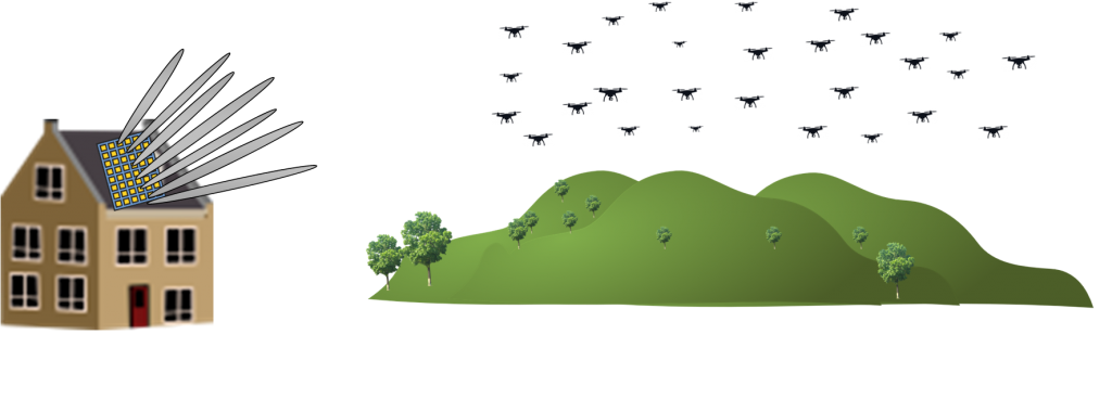
Surveillance/ Search and Rescue/Disaster management: During natural disasters, a network of drones can be quickly deployed to enable the rescue teams to assess the situation in real-time via high-resolution video streaming. Depending on the area to be covered and desired video quality, the sum throughput requirement will be in the order of Gbps. A Massive MIMO array deployed over a ground vehicle or a large aerial vehicle can be used for serving a swarm of drones.
Aerial survey: A swarm of drones can be used for high-resolution aerial imagery of several kilometers of landscape. There are many uses of aerial survey, including state governance, city planning, 3D cartography, and crop monitoring. Massive MIMO can be an enabler for such high throughput and long-range applications.
Backhaul for flying base stations: During emergency situations and heavy traffic conditions, UAVs could be used as flying base stations to provide wireless connectivity to the cellular users. A Massive MIMO base station can act as a high-capacity backhaul to a large number of flying base stations.
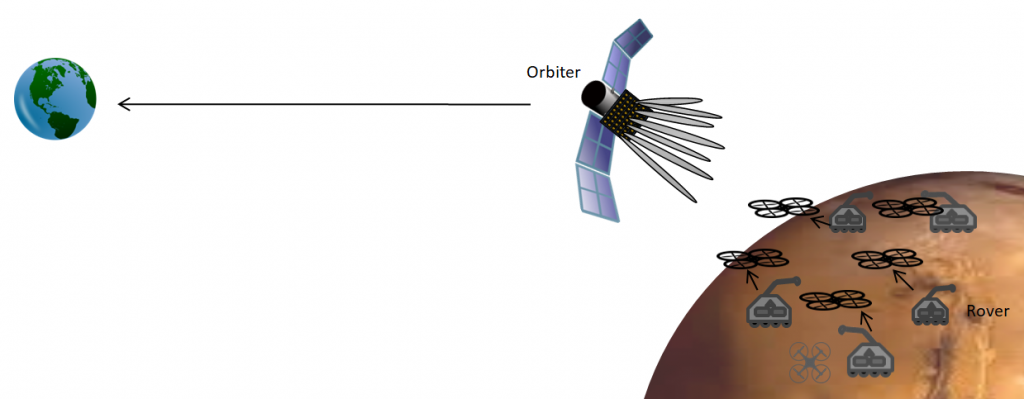
Space exploration: Currently, it takes several hours to receive a photo taken by the Curiosity Mars rover. It is possible to use Massive MIMO to reduce the overall transmission delay. For example, by using a massive antenna array deployed in an orbiter (see the above figure), a swarm of drones and rovers roaming on the surface of another planet can send videos and images to earth. The array can be used to spatially multiplex the uplink transmission from the drones (and possibly the rovers) to the orbiter. Note that the distance between the Mars surface and the orbiter is about 400 km. If the drones fly at an altitude of a few hundred meters and spread out over the region with a few hundred kilometers of radius, the angular resolution of the array is sufficient for spatial multiplexing. The array can be used to transmit the collected images and videos to earth by exploiting the array gain. This might sound like a science fiction, but NASA is already developing a 256 element antenna array for future Mars rovers to enable direct communication with the earth.


 After the
  MAMMOET (Massive MIMO for Efficient Transmission) was the first major research project on Massive MIMO that was funded by the European Union. The project took place 2014-2016 and you might have heard about its outcomes in terms of the first