Category Archives: Technical insights

Are Pilots and Data Transmitted With the Same Power?

The user terminals in reciprocity-based Massive MIMO transmit two types of uplink signals: data and pilots (a.k.a. reference signals). A terminal can potentially transmit these signals using different power levels. In the book Fundamentals of Massive MIMO, the pilots are always sent with maximum power, while the data is sent with a user-specific power level that is optimized to deliver a certain per-user performance. In the book Massive MIMO networks, the uplink power levels are also optimized, but under another assumption: each user must assign the same power to pilots and data.

Moreover, there is a series of research papers (e.g., Ref1, Ref2, Ref3) that treat the pilot and data powers as two separate optimization variables that can be optimized with respect to some performance metric, under a constraint on the total energy budget per transmission/coherence block. This gives the flexibility to “move” power from data to pilots for users at the cell edge, to improve the channel state information that the base station acquires and thereby the array gain that it obtains when decoding the data signals received over the antennas.

In some cases, it is theoretically preferable to assign, for example, 20 dB higher power to pilots than to data. But does that make practical sense, bearing in mind that non-linear amplifiers are used and the peak-to-average-power ratio (PAPR) is then a concern? The answer depends on how the pilots and data are allocated over the time-frequency grid. In OFDM systems, which have an inherently high PAPR, it is discouraged to have large power differences between OFDM symbols (i.e., consecutive symbols in the time domain) since this will further increase the PAPR. However, it is perfectly fine to assign the power in an unequal manner over the subcarriers.

In the OFDM literature, there are two elementary ways to allocate pilots: block and comb type arrangements. These are illustrated in the figure below and some early references on the topic are Ref4, Ref5, Ref6.

(a): In the block type arrangement, at a given OFDM symbol time, all subcarriers either contain pilots or data. It is then preferable for a user terminal to use the same transmit power for pilots and data, to not get a prohibitively high PAPR. This is consistent with the assumptions made in the book Massive MIMO networks.

(b): In the comb type arrangement, some subcarriers always contain pilots and other subcarriers always contain data. It is then possible to assign different power to pilots and data at a user terminal. The power can be moved from pilot subcarriers to data subcarriers or vice versa, without a major impact on the PAPR. This approach enables the type of unequal pilot and data power allocations considered in Fundamentals of Massive MIMO or research papers that optimize the pilot and data powers under a total energy budget per coherence block.

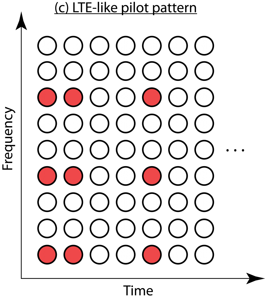
The downlink in LTE uses a variation of the two elementary pilot arrangements, as illustrated in (c). It is easiest described as a comb type arrangement where some pilots are omitted and replaced with data. The number of omitted pilots depend on how many antenna ports are used; the more antennas, the more similar the pilot arrangement becomes to the comb type. Hence, unequal pilot and power allocation is possible in LTE but maybe not as easy to implement as described above. 5G has a more flexible frame structure but supports the same arrangements as LTE.

In summary, uplink pilots and data can be transmitted at different power levels, and this flexibility can be utilized to improve the performance in Massive MIMO. It does, however, require that the pilots are arranged in practically suitable ways, such as the comb type arrangement.

UAVs Prepare for Take-off With Massive MIMO

Drones could shape the future of technology, especially if provided with reliable command and control (C&C) channels for safe and autonomous flying, and high-throughput links for multi-purpose live video streaming. Some months ago, Prabhu Chandhar’s guest post discussed the advantages of using massive MIMO to serve drone – or unmanned aerial vehicle (UAV) – users. More recently, our Paper 1 and Paper 2 have quantified such advantages under the realistic network conditions specified by the 3GPP. While demonstrating that massive MIMO is instrumental in enabling support for UAV users, our works also show that merely upgrading existing base stations (BS) with massive MIMO might not be enough to provide a reliable service at all UAV flying heights. Indeed, hardware solutions need to be complemented with signal processing enhancements through all communications phases, namely, 1) UAV cell selection and association, 2) downlink BS-to-UAV transmissions, and 3) uplink UAV-to-BS transmissions. These are outlined below.

1. UAV cell selection and association

As depicted in Figure 1(a), most existing cellular BSs create a fixed beampattern towards the ground. Thanks to this, ground users tend to perceive a strong signal strength from nearby BSs, which they use for connecting to the network. Instead, aerial users such as the red drone in Figure 1(a) only receive weak sidelobe-generated signals from a nearby BS when flying above it. This results in a deployment planning issue as illustrated in Figure 1(b), where due to the radiation of a strong sidelobe, the tri-sector BSs located in the origin can be the preferred server for far-flung UAVs (red spots). Consequently, these UAVs might experience strong interference, since they perceive signals from a multiplicity of BSs with similar power.

Figure 1. (a) Illustration of a downtilted cellular BS and its beampattern: low (blue) UAV receives strong main lobe signals, whereas high (red) drone only receives weak sidelobe-generated signals. (b) 150-meter-high UAVs (red dots) associated with a three-cell BS site located at the origin and pointing at 30°, 150°, and 270°. The three BSs of each cellular site (orange squares) generate ground cells represented by hexagons.

On the other hand, thanks to their capability of beamforming the synchronization signals used for user association, massive MIMO systems ensure that aerial users generally connect to a nearby BS. This optimized association enhances the robustness of the mobility procedures, as well as the downlink and uplink data phases.

2. Downlink BS-to-UAV transmissions

During the downlink data phase, UAV users are very sensitive to the strong inter-cell interference generated from a plurality of BSs, which are likely to be in line-of-sight. This may result in performance degradation, preventing UAVs from receiving critical C&C information, which has an approximate rate requirement of 60-100 kbps. Indeed, Figure 2 shows how conventional cellular networks (‘SU’) can only guarantee 100 kbps to a mere 6% of the UAVs flying at 150 meters. A conventional massive MIMO system (‘mMIMO’) enhances the data rates, albeit only 33% of the UAVs reach 100 kbps when they fly at 300 meters. This is due to a well-known effect: pilot contamination. Such an effect is particularly severe in scenarios with UAV users, since they can create strong uplink interference to many line-of-sight BSs simultaneously. In contrast, the pilot contamination decays much faster with distance for ground UEs.

In a nutshell, Figure 2 tells us that complementing conventional massive MIMO with explicit inter-cell interference suppression (‘mMIMO w/ nulls’) is essential when supporting high UAVs. In a ‘mMIMO w/ nulls’ system, BSs incorporate additional signal processing features that enable them to perform a twofold task. First, leveraging channel directionality, BSs can spatially separate non-orthogonal pilots transmitted by different UAVs. Second, by dedicating a certain number of spatial degrees of freedom to place radiation nulls, BSs can mitigate interference on the directions corresponding to users in other cells that are most vulnerable to the BS’s interference. Indeed, these additional capabilities dramatically increase the percentage of UAVs that meet the 100 kbps requirement when these are flying at 300 m, from 33% (‘mMIMO’) to a whopping 98% (‘mMIMO w/ nulls’).

Figure 2. Percentage of UAVs with a downlink C&C rate above 100 kbps for three representative UAV heights. ‘SU’ denotes a conventional cellular network with a single antenna port, ‘mMIMO’ represents a system with 8×8 dual-polarized antenna arrays and 128 antenna ports, and ‘mMIMO w/ nulls’ complements the latter with additional space-domain inter-cell interference suppression techniques.

3. Uplink UAV-to-BS transmissions

Unlike the downlink, where UAVs should be protected to prevent a significant performance degradation, it is the ground users who we should care about in the uplink. This is because line-of-sight UAVs can generate strong interference towards many BSs, therefore overwhelming the weaker signals transmitted by non-line-of-sight ground users. The consequences of such a phenomenon are illustrated in Figure 3, where the uplink rates of ground users plummet as the number of UAVs increases.

Again, ‘mMIMO w/nulls’ – incorporating additional space-domain inter-cell interference suppression capabilities – can solve the above issue and guarantee a better performance for legacy ground users.

Figure 3. Average uplink rates of ground users when the number of UAVs per cell grows. ‘SU’ denotes a conventional cellular network with a single antenna port, ‘mMIMO’ represents a system with 8×8 antenna dual-polarized antenna arrays and 128 antenna ports, and ‘mMIMO w/ nulls’ complements the latter with additional space-domain inter-cell interference suppression techniques.

Overall, the efforts towards realizing aerial wireless networks are just commencing, and massive MIMO will likely play a key role. In the exciting era of fly-and-connect, we must revisit our understanding of cellular networks and develop novel architectures and techniques, catering not only for roads and buildings, but also for the sky.

Pilot Contamination is Not Captured by the MSE

Pilot contamination used to be seen as the key issue with the Massive MIMO technology, but thanks to a large number of scientific papers we now know fairly well how to deal with it. I outlined the main approaches to mitigate pilot contamination in a previous blog post and since then the paper Massive MIMO has unlimited capacity has also been picked up by science news channels.

When reading papers on pilot (de)contamination written by many different authors, I’ve noticed one recurrent issue: the mean-squared error (MSE) is used to measure the level of pilot contamination. A few papers only plot the MSE, while most papers contain multiple MSE plots and then one or two plots with bit-error-rates or achievable rates. As I will explain below, the MSE is a rather poor measure of pilot contamination since it cannot distinguish between noise and pilot contamination.

A simple example

Suppose the desired uplink signal is received with power p and is disturbed by noise with power (1-a) and interference from another user with power a. By varying the variable a between 0 and 1 in this simple example, we can study how the performance changes when moving power from the noise to the interference, and vice versa.

By following the standard approach for channel estimation based on uplink pilots (see Fundamentals of Massive MIMO), the MSE for i.i.d. Rayleigh fading channels is

    $$\textrm{MSE} = \frac{p}{p+(1-a)+a} = \frac{p}{p+1}, $$

which is independent of a and, hence, does not care about whether the disturbance comes from noise or interference. This is rather intuitive since both the noise and interference are additive i.i.d. Gaussian random variables in this example. The important difference appears in the data transmission phase, where the noise takes a new independent realization and the interference is strongly correlated with the interference in the pilot phase, because it is the product of a new scalar signal and the same channel vector.

To demonstrate the important difference, suppose maximum ratio combining is used to detect the uplink data. The effective uplink signal-to-interference-and-noise-ratio (SINR) is

    $$\textrm{SINR} = \frac{p(1-\textrm{MSE}) M}{p+1+a M \cdot \textrm{MSE}}$$

where M is the number of antennas. For any given MSE value, it now matters how it was generated, because the SINR is a decreasing function of a. The term a M  \cdot \textrm{MSE} is due to pilot contamination (it is often called coherent interference) and is proportional to the interference power $a$. When the number of antennas is large, it is far better to have more noise during the pilot transmission than more interference!

Implications

Since the MSE cannot separate noise from interference, we should not try to measure the effectiveness of a “pilot decontamination” algorithm by considering the MSE. An algorithm that achieves a low MSE can potentially be mitigating the noise, leaving the interference unaffected. If that is the case, the pilot contamination term $a M  \cdot \textrm{MSE}$ will remain. The MSE has been used far too often when evaluating pilot decontamination algorithms, and a few papers (I found three while writing this post) did only consider the MSE, which opens the door for questioning their conclusions.

The right methodology is to compute the SINR (or some other performance indicator in the data phase) with the proposed pilot decontamination algorithm and with competing algorithms. In that case, we can be sure that the full impact of the pilot contamination is taken into account.

Disadvantages with TDD

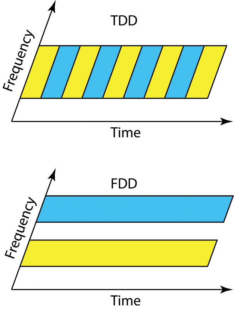
LTE was designed to work equally well in time-division duplex (TDD) and frequency division duplex (FDD) mode, so that operators could choose their mode of operation depending on their spectrum licenses. In contrast, Massive MIMO clearly works at its best in TDD, since the pilot overhead is prohibitive in FDD (even if there are some potential solutions that partially overcome this issue).

Clearly, we will see a larger focus on TDD in future networks, but there are some traditional disadvantages with TDD that we need to bear in mind when designing these networks. I describe the three main ones below.

Link budget

Even if we allocate the same amount of time-frequency resources to uplink and downlink in TDD and FDD operation, there is an important difference. We transmit over half the bandwidth all the time in FDD, while we transmit over the whole bandwidth half of the time in TDD.  Since the power amplifier is only active half of the time, if the peak power is the same, the average radiated power is effectively cut in half. This means that the SNR is 3 dB lower in TDD than in FDD, when transmitting at maximum peak power.

Massive MIMO systems are generally interference-limited and uses power control to assign a reduced transmit power to most users, thus the impact of the 3 dB SNR loss at maximum peak power is immaterial in many cases. However, there will always be some unfortunate low-SNR users (e.g., at the cell edge) that would like to communicate at maximum peak power in both uplink and downlink, and therefore suffer from the 3 dB SNR loss. If these users are still able to connect to the base station, the beamforming gain provided by Massive MIMO will probably more than compensate for the loss in link budget as compared single-antenna systems. One can discuss if it should be the peak power or average radiated power that is constrained in practice.

Guard period

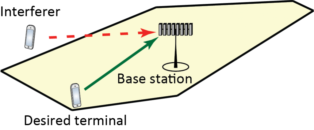
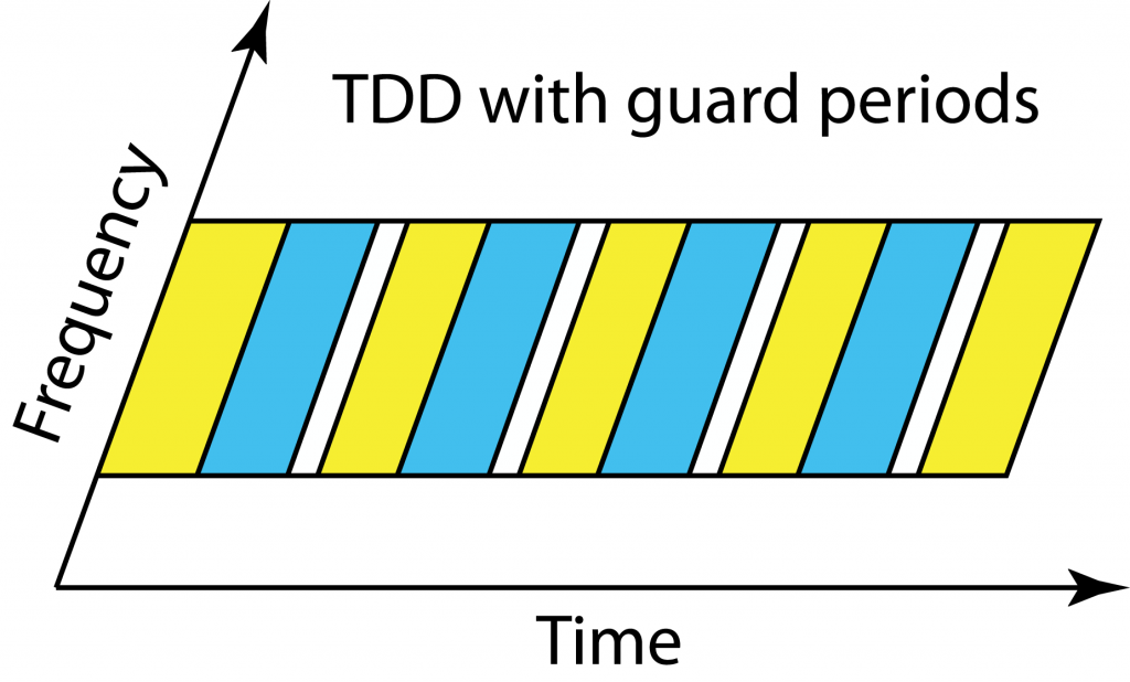
Everyone in the cell should operate in uplink and downlink mode at the same time in TDD. Since the users are at different distances from the base station and have different delay spreads, they will receive the end of the downlink transmission block at different time instances. If a cell center user starts to transmit in the uplink immediately after receiving the full downlink block, then users at the cell edge will receive a combination of the delayed downlink transmission and the cell center users’ uplink transmissions. To avoid such uplink-downlink interference, there is a guard period in TDD so that all users wait with uplink transmission until the outmost users are done with the downlink.

In fact, the base station gives every user a timing bias to make sure that when the uplink commences, the users’ uplink signals are received in a time-synchronized fashion at the base station. Therefore, the outmost users will start transmitting in the uplink before the cell center users. Thanks to this feature, the largest guard period is needed when switching from downlink to uplink, while the uplink to downlink switching period can be short. This is positive for Massive MIMO operation since we want to use uplink CSI in the next downlink block, but not the other way around.

The guard period in TDD must become larger when the cell size increases, meaning that a larger fraction of the transmission resources disappears. Since no guard periods are needed in FDD, the largest benefits of TDD will be seen in urban scenarios where the macro cells have a radius of a few hundred meters and the delay spread is short.

Inter-cell synchronization

We want to avoid interference between uplink and downlink within a cell and the same thing applies for the inter-cell interference. The base stations in different cells should be fairly time-synchronized so that the uplink and downlink take place at the same time; otherwise, it might happen that a cell-edge user receives a downlink signal from its own base station and is interfered by the uplink transmission from a neighboring user that connects to another base station.

This can also be an issue between telecom operators that use neighboring frequency bands. There are strict regulations on the permitted out-of-band radiation, but the out-of-band interference can anyway be larger than the desired inband signal if the interferer is very close to the receiving inband user. Hence, it is preferred that the telecom operators are also synchronizing their switching between uplink and downlink.

Summary

Massive MIMO will bring great gains in spectral efficiency in future cellular networks, but we should not forget about the traditional disadvantages of TDD operation: 3 dB loss in SNR at peak power transmission, larger guard periods in larger cells, and time synchronization between neighboring base stations.

Are 1-bit ADCs Meaningful?

Contemporary base stations are equipped with analog-to-digital converters (ADCs) that take samples described by 12-16 bits. Since the communication bandwidth is up to 100 MHz in LTE Advanced, a sampling rate of a 500 Msample/s is quite sufficient for the ADC. The power consumption of such an ADC is at the order of 1 W. Hence, in a Massive MIMO base station with 100 antennas, the ADCs would consume around 100 W!

ADC SymbolFortunately, the 1600 bit/sample that are effectively produced by 100 16-bit ADCs are much more than what is needed to communicate at practical SINRs. For this reason, there is plenty of research on Massive MIMO base stations equipped with lower-resolution ADCs. The use of 1-bit ADCs has received particular attention. Some good paper references are provided in a previous blog post: Are 1-bit ADCs sufficient? While many early works considered narrowband channels, recent papers (e.g., Quantized massive MU-MIMO-OFDM uplink) have demonstrated that 1-bit ADCs can also be used in practical frequency-selective wideband channels. I’m impressed by the analytical depth of these papers, but I don’t think it is practically meaningful to use 1-bit ADCs.

Do we really need 1-bit ADCs?

I think the answer is no in most situations. The reason is that ADCs with a resolution of around 6 bits strike a much better balance between communication performance and power consumption. The state-of-the-art 6-bit ADCs are already very energy-efficient. For example, the paper “A 5.5mW 6b 5GS/S 4×-lnterleaved 3b/cycle SAR ADC in 65nm CMOS” from ISSCC 2015 describes a 6-bit ADC that consumes 5.5 mW and has a huge sampling rate of 5 Gsample/s, which is sufficient even for extreme mmWave applications with 1 GHz of bandwidth. In a base station equipped with 100 of these 6-bit ADCs, less than 1 W is consumed by the ADCs. That will likely be a negligible factor in the total power consumption of any base station, so what is the point in using a lower resolution than that?

The use of 1-bit ADCs comes with a substantial loss in communication rate. In contrast, there is a consensus that Massive MIMO with 3-5 bits per ADC performs very close to the unquantized case (see Paper 1Paper 2, Paper 3, Paper 4Paper 5). The same applies for 6-bit ADCs, which provide an additional margin that protects against strong interference. Note that there is nothing magical with 6-bit ADCs; maybe 5-bit or 7-bit ADCs will be even better, but I don’t think it is meaningful to use 1-bit ADCs.

Will 1-bit ADCs ever become useful?

To select a 1-bit ADC, instead of an ADC with higher resolution, the energy consumption of the receiving device must be extremely constrained. I don’t think that will ever be the case in base stations, because the power amplifiers are dominating their energy consumption. However, the case might be different for internet-of-things devices that are supposed to run for ten years on the same battery. To make 1-bit ADCs meaningful, we need to greatly simplify all the other hardware components as well. One potential approach is to make a dedicated spatial-temporal waveform design, as described in this paper.